Junction surface contact area and rigidity confirming method based on surface fitting

A contact area and surface fitting technology, applied in special data processing applications, instruments, electrical digital data processing, etc., can solve the problem of limiting the size of the calculation area and calculation efficiency, without considering the geometric shape, that is, the waviness and the contact stiffness of the combined surface Affecting the law, divorced from reality and other issues

Active Publication Date: 2014-10-01
XI AN JIAOTONG UNIV
View PDF1 Cites 21 Cited by
  • Summary
  • Abstract
  • Description
  • Claims
  • Application Information

AI Technical Summary

Problems solved by technology

This research on microscopic contact behavior is based on many assumptions. Although the model has been developing and perfecting, the existing contact models basically still have the following problems: 1. The shape of the asperity is assumed to be Spherical or other simple shapes, which are far from reality; 2. When studying the contact behavior of the entire surface, it is assumed that the surface profile height distribution obeys a certain function distribution such as a normal distribution, and the statistical parameters of surface roughness such as the average radius of curvature are used. Starting from the real surface; 3. The research on the contact stiffness at the joint surface is limited to the rough scale level, without considering the influence of geometric shape, namely waviness, and macroscopic shape error on the contact stiffness of the joint surface
The existing finite element method can use real surface measurement data to study the contact problem, but because the finite element calculation needs to be divided into extremely fine grids, the size of the calculation area and the calculation efficiency are severely limited

Method used


Image

  • Junction surface contact area and rigidity confirming method based on surface fitting
  • Junction surface contact area and rigidity confirming method based on surface fitting
  • Junction surface contact area and rigidity confirming method based on surface fitting

Examples


Embodiment Construction

[0048] The present invention is described in detail below in conjunction with accompanying drawing:

[0049] A method for determining the contact area and stiffness of a joint surface based on surface fitting, comprising the following steps:

[0050] 1) Measurement of real shape and function representation

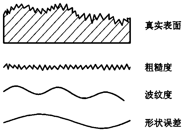
[0051] 1.1) Classification of joint surface morphology: such as figure 1 As shown, the mechanical bonding surface is divided into three levels of roughness, waviness, and shape error according to the wavelength from small to large. The peak-to-peak spacing is less than 1mm. Convex body, and assuming that the shape of the micro-convex body is the same; the surface undulation with the distance between the peaks within the range of 1mm to 10mm is regarded as waviness; the surface undulation with the distance between the peaks exceeding 10mm is regarded as the surface shape error deal with;

[0052] 1.2) Asperity function fitting: use confocal microscope to observe the aspe...


PUM


Abstract

Disclosed is a junction surface contact area and rigidity confirming method based on surface fitting. The junction surface contact area and rigidity confirming method based on the surface fitting includes: firstly, using confocal microscopy and three coordinate measuring to measure micro bulge morphology, external waviness and shape error of a mechanical junction surface, performing fitting on obtained point cloud data by using a binary high order function, and accordingly obtaining a final analysis formula of a contact surface; secondly, judging positions and contact directions of micro bulge contact points, then performing Hertz contact calculation on each single contact point, and calculating contact deformation and contact area under functions of force; finally, calculating overall contact area and contact rigidity of the contact surface so as to obtain total contact area and contact rigidity in each direction. Compared with a traditional analysis method, the junction surface contact area and rigidity confirming method based on the surface fitting has the advantage of approaching real morphology. Compared with a finite element method, the junction surface contact area and rigidity confirming method based on the surface fitting can enlarge the contact area which can be calculated.

Description

technical field [0001] The invention belongs to the field of mechanical joint surface mechanics, and in particular relates to a method for determining the contact area and stiffness of a joint surface based on curved surface fitting. Background technique [0002] There are a large number of joint surfaces in complex mechanical systems such as machine tools, gas turbines, and automobile engines, which destroy the continuity of the mechanical system structure and affect the overall performance of the mechanical system to a large extent. The connection characteristics of the joint surface present a certain degree of nonlinearity, and introducing the characteristic parameter model of the joint surface into the modeling process of the whole system can effectively improve the performance prediction ability of the whole machine in the product design stage. Therefore, the accurate construction of the joint surface characteristic parameter model will provide a theoretical basis for t...

Claims


Application Information

Patent Timeline
Patent Type & Authority Applications(China)
IPC IPC(8): G06F17/50
Inventor 张进华刘伟强洪军朱林波吴凤
Owner XI AN JIAOTONG UNIV
Why Eureka
Try Eureka