Microgroove cable

A cable and micro-groove technology, which is applied in the direction of power cables, insulated cables, cables, etc., can solve the problems of inconvenient construction and maintenance, easily damaged optical fiber performance, and easy loose shape of optical fiber ribbons, etc., and achieve high qualified rate of finished products and stable product quality , the effect of high product density

Inactive Publication Date: 2014-10-01
STATE GRID SHANDONG ELECTRIC POWER +1
View PDF5 Cites 20 Cited by
  • Summary
  • Abstract
  • Description
  • Claims
  • Application Information

AI Technical Summary

Problems solved by technology

It has achieved the following beneficial effects: greatly reducing the occupation of space resources, effectively reducing the consumption of raw materials, significantly saving costs, reducing user expenses, simplifying the production process, and reducing the investment in production equipment However, it has the following main defects: (1) it needs to use optical fiber ribbons, and a large amount of ultraviolet curing or thermal curing resin needs to be added in the process of forming optical fiber ribbons from optical fibers. Expensive paralleling equipment is required, which consumes a lot of electricity; (2) The fiber optic ribbon is wound around the filler body, and the fiber optic ribbon is easily loose and difficult to form. It brings great inconvenience to construction and maintenance; (3) It is not easy to branch. During construction and application, it is necessary to tear off the protective layer of the optical fiber ribbon and tear the optical fiber ribbon after the optical cable is cut, so that the required optical fiber can be taken out. This affects unused fibers and can easily damage the performance of unused fibers

Method used


Image

  • Microgroove cable
  • Microgroove cable
  • Microgroove cable

Examples


Embodiment 1

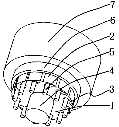
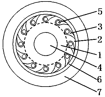
[0021] please see Figure 1 to Figure 2 A micro-groove cable, comprising a skeleton body 1, 12 bone leaves 2, 12 skeleton grooves 3, a reinforcement 4, a plurality of cable cores 5, a protective layer 6, a sheath layer 7, a skeleton body, and bone leaves 1. The skeleton groove is integrally formed, the bone leaf is located on the edge of the skeleton body, the reinforcement is located in the center of the skeleton body, the skeleton groove is formed between adjacent bone leaves, the cable core is located in the skeleton groove, and the protective layer is covered outside the bone leaf. The sheath layer is extrusion-coated outside the protective layer, and it is characterized in that: the outer edge of the bone leaf and the outer edge of the skeleton groove are located on the side of the same cylinder, each skeleton groove has an opening, and the opening is toward the shield In the direction of the jacket layer, the width of the skeleton groove at the opening is the smallest, a...

Embodiment 2

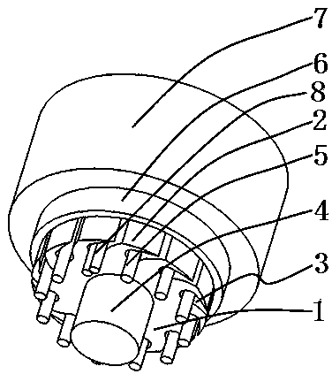
[0023] please see image 3 and Figure 4 , and refer to figure 1 and figure 2 , a micro-groove cable, comprising a skeleton body 1, 12 bone leaves 2, 12 skeleton grooves 3, a reinforcement 4, a plurality of cable cores 5, a protective layer 6, a sheath layer 7, the skeleton body, the bone leaves 1. The skeleton groove is integrally formed, the bone leaf is located on the edge of the skeleton body, the reinforcement is located in the center of the skeleton body, the skeleton groove is formed between adjacent bone leaves, the cable core is located in the skeleton groove, and the protective layer is covered outside the bone leaf. The sheath layer is extrusion-coated outside the protective layer, and it is characterized in that: the outer edge of the bone leaf and the outer edge of the skeleton groove are located on the side of the same cylinder, each skeleton groove has an opening, and the opening is toward the shield In the direction of the jacket layer, the width of the ske...


PUM


Abstract

The invention belongs to the technical field of cables and particularly relates to a microgroove cable, which comprises a framework body, a plurality of framework blades, a plurality of framework slots, a reinforcing piece, a plurality of cable cores, a protective layer and a protective sleeve layer, wherein the framework body, the framework blades, and the framework slots are integrally formed; the framework blades are positioned on the edge of the framework body; the reinforcing piece is positioned in the center of the framework body; one framework slot is formed between each two adjacent framework blades; the cable cores are positioned in the framework slots; the framework blades are coated with the protective layer; the protective layer is coated with the protective sleeve layer in an extrusion manner; the microgroove cable is characterized in that the outer edges of the framework blades, and the outer edges of the framework slots are positioned on the side surface of the same cylinder, and at any cross section, the midpoint of the connecting line of the two ends of the opening of each framework slot and the connecting line of the top point of the bottom of each framework slot do not pass through the center of the reinforcing piece; all the framework slots are in the same direction. The microgroove cable has the main benefits as follows: the microgroove cable is easy to produce, higher in qualification rate of finished products, low in production equipment input, less in resource consumption, higher in product density, and more stable in product quality.

Description

technical field [0001] The invention belongs to the technical field of cables, in particular to a microgroove cable. Background technique [0002] With the rapid development of the communication industry, the society's demand for optical cables is increasing. On the other hand, with the rapid development of industrialization, the resources consumed by all walks of life are also increasing. Therefore, the world calls for low-carbon environmental protection; therefore, in the wire and cable industry, various cables tend to be miniaturized, highly integrated, Densification. Chinese patent CN101393310A discloses an optical fiber ribbon cable, which is at least composed of a filler, an optical fiber ribbon, a protective layer and a sheath; the optical fiber ribbon surrounds and covers the filler body, and the protective layer surrounds and covers the optical fiber ribbon. The sheath wraps around the protective layer. The filling body is a single rod-shaped material or a compo...

Claims


Application Information

Patent Timeline
Patent Type & Authority Applications(China)
IPC IPC(8): H01B7/17H01B7/18H01B9/00G02B6/44
Inventor 蔡洪祥
Owner STATE GRID SHANDONG ELECTRIC POWER
Why Eureka
Try Eureka