A motor system with the ability to reduce common-mode interference
A common mode interference and capability technology, applied in the control system, AC motor control, electrical components and other directions, can solve the problem of common mode interference in the motor system, and achieve the effect of improving electromagnetic compatibility, reducing changes, and reducing common mode interference.
- Summary
- Abstract
- Description
- Claims
- Application Information
AI Technical Summary
Problems solved by technology
Method used
Image
Examples
Embodiment 1
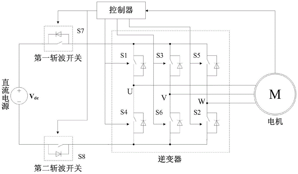
[0041] The circuit topology of this embodiment is as figure 2 As shown, taking the three-phase as an example, a switching tube is connected in series on the positive and negative terminals of the DC voltage (the chopper switch connected to the positive pole is S7, and the chopper switch connected to the negative pole is S8); the chopper switches S7 and S8 are followed by Into a full-bridge inverter circuit composed of 6 switching tubes, in which S1 and S4 form the upper and lower arms of the first bridge arm, S3 and S6 form the upper and lower arms of the second bridge arm, and S5 and S2 form the upper and lower arms of the third bridge arm arm.
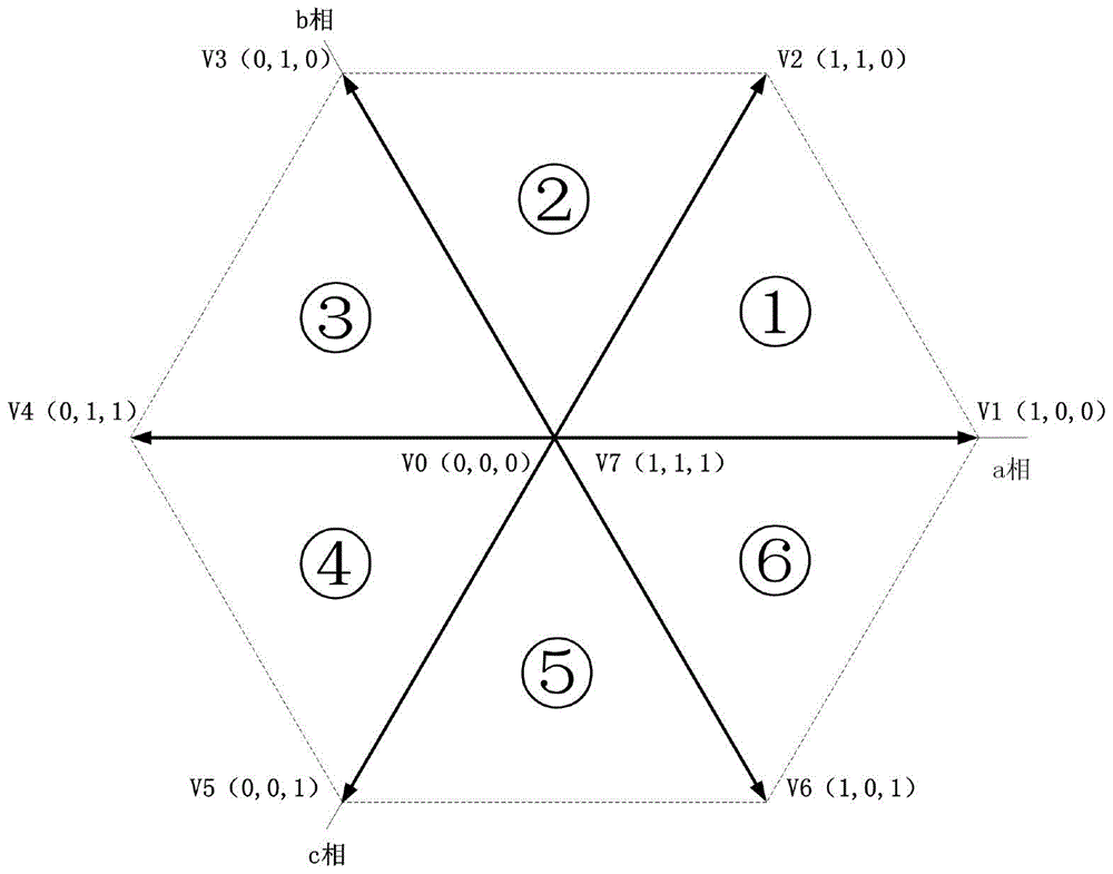
[0042] When the zero-voltage space vector acts, the common-mode voltage of the motor is . If the DC power supply and the inverter are disconnected at the same time under the action of the zero-voltage space vector, the motor power supply will be in a high-impedance state at this time, and the potential of the motor is completely dete...
Embodiment 2
[0050] In this embodiment, only the chopper switch S7 at the high voltage is selected for control, and the other chopper switch is always on. In addition, in order to reduce costs and simplify control, this chopper switch can be omitted, and the negative pole of the DC power supply and the inverter The negative terminal is directly connected.
[0051] Taking the three-phase as an example, a switch tube is connected in series with the positive terminal of the DC voltage (the chopper switch is S7); behind the chopper switch S7, a full-bridge inverter circuit composed of six switch tubes is connected, among which, S1 and S4 are composed of The upper and lower arms of the first bridge arm, S3 and S6 form the upper and lower arms of the second bridge arm, and S5 and S2 form the upper and lower arms of the third bridge arm.
[0052] When the zero-voltage space vector V7 acts, the common-mode voltage of the motor is . If the connection with the DC power supply is disconnected at the...
Embodiment 3
[0059] In this embodiment, only the chopper switch S8 at the low voltage is selected for control, and the other chopper switch is always on. In addition, in order to reduce costs and simplify control, this chopper switch can be omitted, and the positive pole of the DC power supply and the inverter The positive ends are directly connected.
[0060] Also taking the three-phase as an example, a switch tube is connected in series on the negative terminal of the DC voltage (the chopper switch is S8); the chopper switch S8 is connected to a full-bridge inverter circuit composed of 6 switch tubes, among which, S1 and S4 are composed of The upper and lower arms of the first bridge arm, S3 and S6 form the upper and lower arms of the second bridge arm, and S5 and S2 form the upper and lower arms of the third bridge arm.
[0061] When the zero-voltage space vector V0 acts, the common-mode voltage of the motor is . If the connection with the DC power supply is disconnected at the same ti...
PUM
 Abstract
Description
Claims
Application Information
 - R&D
- Intellectual Property
- Life Sciences
- Materials
- Tech Scout
- Unparalleled Data Quality
- Higher Quality Content
- 60% Fewer Hallucinations
Browse by: Latest US Patents, China's latest patents, Technical Efficacy Thesaurus, Application Domain, Technology Topic, Popular Technical Reports.
© 2025 PatSnap. All rights reserved.Legal|Privacy policy|Modern Slavery Act Transparency Statement|Sitemap|About US| Contact US: help@patsnap.com


