Microwave vco direct modulation high linear frequency modulation signal generating circuit

A technology of frequency modulation signal and generating circuit, applied in the direction of pulse shaping, etc., can solve the problems of complex circuit implementation, low cost, narrow frequency sweep bandwidth, etc., to improve the linear accuracy of frequency sweep, unrestricted frequency sweep rate, and reduce distance measurement effect of error

Active Publication Date: 2016-08-17
10TH RES INST OF CETC
View PDF6 Cites 2 Cited by
  • Summary
  • Abstract
  • Description
  • Claims
  • Application Information

AI Technical Summary

Problems solved by technology

At present, linear sweep signals are mainly generated by frequency synthesizers or directly modulated by microwave voltage-controlled oscillators (VCO). The former can achieve good linearity, but the achievable sweep rate is low and the sweep bandwidth is also narrow. The circuit is complicated and the cost is high
Microwave VCO direct modulation has no frequency sweep rate limit, and the sweep bandwidth is only limited by the maximum tuning bandwidth of the VCO. The cost is low, but the sweep linearity is poor, which generally does not meet the requirements, and linearization compensation measures must be used to improve linearity.
Commonly used linearization compensation measures include open-loop compensation and closed-loop compensation. The linearity of open-loop compensation can reach about 5%, which cannot meet the requirements of high-precision ranging
The closed-loop compensation circuit can achieve higher linearity, but the circuit implementation is complex, generally requires digital signal processing, the cost is high, and it is also difficult to achieve high sweep rate and large sweep bandwidth

Method used


Image

  • Microwave vco direct modulation high linear frequency modulation signal generating circuit
  • Microwave vco direct modulation high linear frequency modulation signal generating circuit
  • Microwave vco direct modulation high linear frequency modulation signal generating circuit

Examples


Embodiment Construction

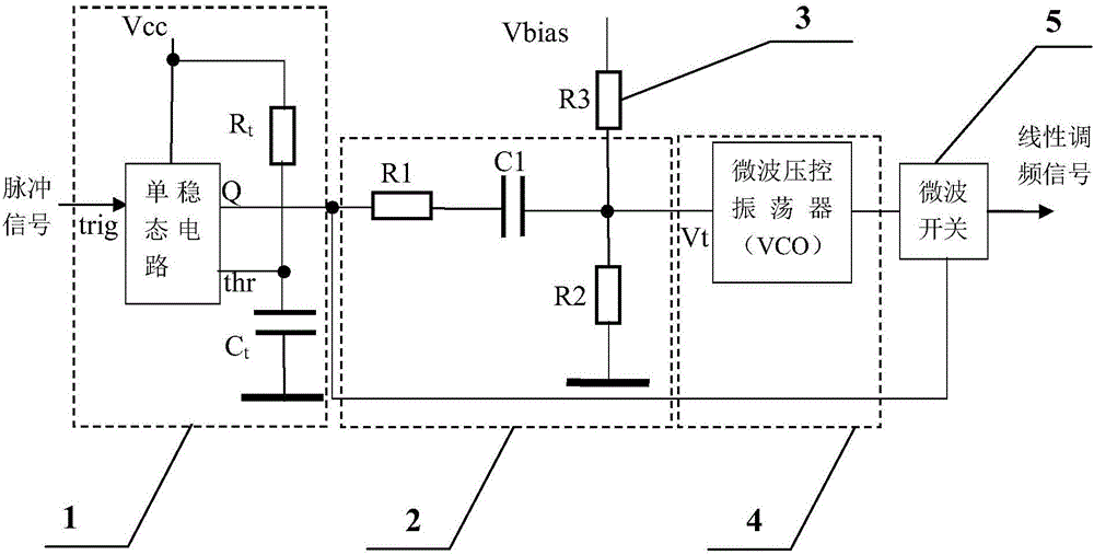
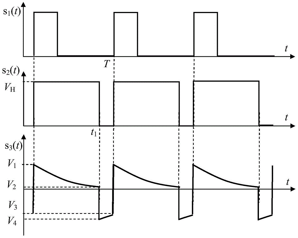
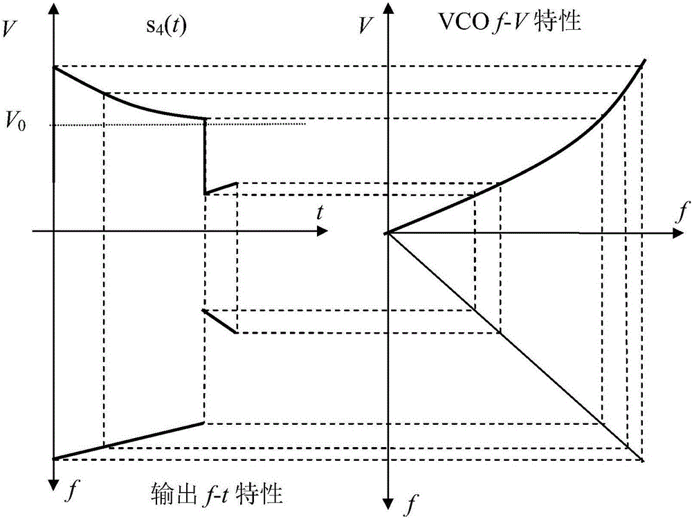
[0018] exist figure 1 In the shown microwave VCO direct modulation high-chirp signal generation circuit, simple pulse shaping and differential circuits can be used to generate periodic nonlinear ramp-down sawtooth wave scanning voltage waveforms, and the microwave VCO can be directly modulated to generate chirp signal output. The circuit includes a monostable pulse shaping circuit 1, a C-R differential circuit 2, a bias resistor 3, a microwave voltage-controlled oscillator VCO4 and a microwave switch 5. The monostable pulse shaping circuit 1 adopts a monostable flip-flop integrated circuit externally connected with a timing resistor R t and timing capacitor C t accomplish. The differential circuit 2 consists of resistors R connected in series between the input terminal and the output terminal in sequence 1 , Differential capacitance C 1 , and a ground resistor R in parallel between the output terminal and ground 2 composition. The differential circuit 2 differentiates th...


PUM


Abstract

A microwave VCO directly modulates a high linear FM signal generating circuit proposed by the present invention, aiming to provide a frequency-modulation continuous-wave radar intermediate frequency with second-order or higher frequency sweep linear accuracy, unlimited sweep rate, and capable of suppressing cross-mixing A microwave chirp signal generation circuit for spurious signals. The present invention is realized through the following technical solutions: the monostable pulse shaping circuit shapes the input periodic pulse signal used to trigger the frequency sweep signal into a pulse signal with a pulse width equal to the frequency sweep time in one cycle, and generates nonlinearity through the C-R differential circuit Ramp down sawtooth voltage signal, superimposed on the DC bias voltage V 0 Above, a frequency-sweeping control voltage signal that compensates with the nonlinear tuning voltage-frequency characteristic of the microwave VCO (4) is formed to control the oscillation frequency of the microwave VCO to change linearly with time. The pulse signal generated by the shaping controls the microwave switch to gate the output of the microwave VCO, and suppresses the interference of the intermediate frequency stray signal generated by the close-range strong echo to the radar.

Description

technical field [0001] The invention relates to a microwave voltage-controlled oscillator (VCO) which is mainly used in frequency-modulated continuous wave (FMCW) radar to directly modulate a high-linear frequency-modulated signal generating circuit. The frequency-time characteristic curve within the frequency sweep time of the cycle has a linear precision above the second order. Background technique [0002] The Linear Frequency Modulation (LFM) signal is a large time-width-bandwidth product obtained through linear frequency modulation. It is also called a Chirp signal. It is the earliest studied and most widely used pulse compression signal. Radar usually adopts a LFM signal to ensure high resolution while increasing the detection distance. FMCW (Frequency Modulated Continuous Wave) frequency-modulated continuous wave system radar has been around for a long time, and its main advantages include low radiation power, high accuracy of distance measurement and speed measureme...

Claims


Application Information

Patent Timeline
Patent Type & Authority Patents(China)
IPC IPC(8): H03K5/04
Inventor 黄建
Owner 10TH RES INST OF CETC
Why Eureka
Try Eureka