Laser cutting equipment for stainless steel chip

A laser cutting, stainless steel technology, applied in laser welding equipment, welding equipment, metal processing equipment and other directions, can solve the problems of high maintenance cost, difficult to meet mass production, low efficiency, etc., to achieve the effect of ensuring position accuracy

Active Publication Date: 2014-10-08
CHANGSHUN GUANGHUA MICRO ELECTRONICS EQUIP ENG CENT
View PDF7 Cites 23 Cited by
  • Summary
  • Abstract
  • Description
  • Claims
  • Application Information

AI Technical Summary

Problems solved by technology

However, this cutting method has huge equipment, low efficiency, and high main

Method used


Image

  • Laser cutting equipment for stainless steel chip
  • Laser cutting equipment for stainless steel chip
  • Laser cutting equipment for stainless steel chip

Examples


Example Embodiment

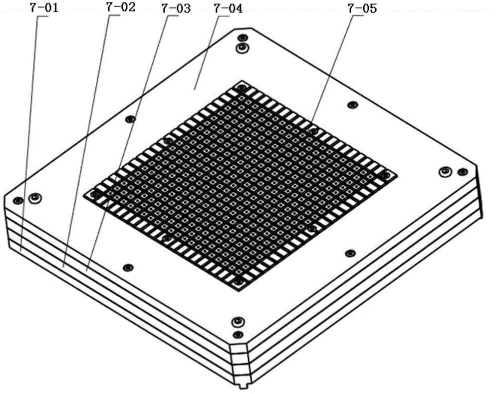
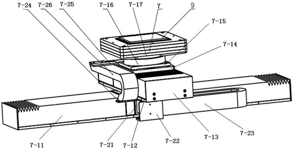
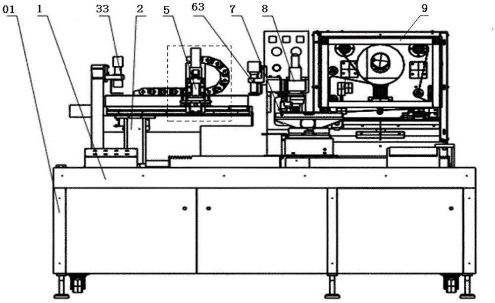
[0055] Such as figure 1 As shown, the automatic positioning device for stainless steel feeding is characterized by including a platform base (1), a feeding platform device (2), a preliminary positioning camera (33), a feeding base (4), and a feeding manipulator (5). ), precision positioning camera (63), adsorption platform (7).

[0056] Such as figure 2 , 3 As shown in 4, the loading platform device 2 includes a bracket 2-21, a loading platform 2-22, an X-direction limit block 2-23, a Y-direction limit block 2-24, and an X-direction photoelectric sensor 2-25 , Y-direction photoelectric sensor 2-27. Y-direction linear motion mechanism includes motor 2-11, motor base 2-12, limit block 2-13, screw 2-14, screw slide 2-15; motor base 2-12 is fixed on platform base 1, The motor 2-11 is fixed on the motor base 2-12, and its output shaft is connected with the lead screw 2-14. The lead screw slide plate 2-15 is installed on the lead screw 2-14. The motor drives the lead screw and drives...


PUM


Abstract

The invention relates to laser cutting equipment for a stainless steel chip. A loading platform device of the laser cutting equipment can carry out Y-direction straight-line motion on a platform base, and the stainless steel chip is placed on the loading platform device. A primary positioning camera is installed above the loading platform device, and used for primary positioning of the stainless steel chip. A loading mechanical hand can carry out X-direction straight-line motion and Y-direction straight-line motion on a loading base and is used for picking the stainless steel chip and placing the stainless steel chip to a suction platform. The suction platform can carry out X-direction straight-line motion, Z-direction straight-line motion and rotary motion on the platform base. A fine positioning camera is fixedly arranged above the suction platform on the platform base and used for adjusting the position of the suction platform to achieve fine positioning of the stainless steel chip. A laser cutting system and a film pasting device are fixed to the platform base and used for achieving cutting and film pasting of the stainless steel chip. The laser cutting equipment is high in integration degree, high in production efficiency, good in cutting quality and capable of well meeting the requirement for producing stainless steel chips on a large scale.

Description

technical field [0001] The invention relates to a stainless steel chip laser cutting equipment. Background technique [0002] Laser cutting is a fast-growing new technology, and has become one of the key technologies for developing emerging industries and transforming traditional manufacturing industries. Laser cutting has been widely used in modern industry due to its wide cutting range, high cutting speed, narrow slit, good cutting quality, small heat-affected zone, and large processing flexibility. Laser cutting technology has also become the most advanced laser processing technology. One of the mature technologies, with the continuous development of laser processing technology, in addition to the application of laser processing in traditional industries, more and more applications in the field of fine processing, such as military industry, electronic product processing, semiconductor Processing fields, etc., these fields put forward higher requirements for laser cutting...

Claims


Application Information

Patent Timeline
IPC IPC(8): B23K26/38B23K26/70
CPCB23K26/0853B23K26/38B23K2101/36
Inventor 张德龙吴玉彬黄波王忠生刘轩郑福志田玉鑫金钊张男男
Owner CHANGSHUN GUANGHUA MICRO ELECTRONICS EQUIP ENG CENT
Why Eureka
Try Eureka