Inner circle slicer

A technology of inner circle slicing and machine base, which is applied in metal processing and other directions, can solve the problems of poor slicing quality, low sensitivity and precision, etc., and achieve the effect of convenient adjustment, simple device setting and firm positioning

Active Publication Date: 2014-10-08
BEIJING DINGCHEN HIGH TECH
View PDF9 Cites 7 Cited by
  • Summary
  • Abstract
  • Description
  • Claims
  • Application Information

AI Technical Summary

Problems solved by technology

[0006] Therefore, the technical problem to be solved by the present invention is to overcome the need to simultaneously drive the transverse drive device to move longitudinally together when the inner circle slicer in the prior art drives the workbench to move longitudinally. The sensitivity and accuracy of the longitudinal adjustment of the circular slicer ar

Method used


Image

  • Inner circle slicer
  • Inner circle slicer
  • Inner circle slicer

Examples


Embodiment 1

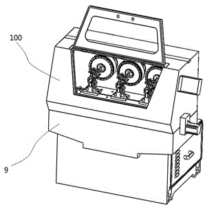
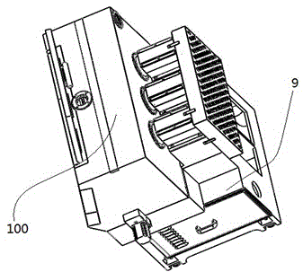
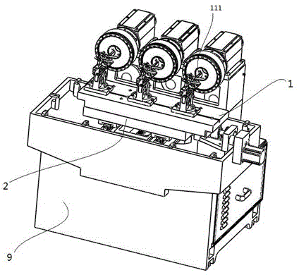
[0101] This embodiment provides a kind of inner circle slicer, such as Figure 1-6 As shown, it includes a base 9, a lower carriage 2 fixedly arranged on the top of the base 9, and an upper carriage 1 installed on the lower carriage 2, and a clip is fixed on the upper carriage 1. A material plate seat holding a material rod 111; the base 9 is also provided with a first feed mechanism for driving the lower carriage 2 and further driving the upper carriage 1 to move along the first direction, and A second feeding mechanism for driving the upper carriage 1 to move in the second direction relative to the lower carriage 2, the second feeding mechanism drives the lower carriage 2 after the first feeding mechanism No follow-up occurs when the carriage 2 moves along the first direction.

[0102] In this example, if Figure 7 , Figure 8 , Figure 9 with Figure 10 As shown, the above-mentioned first fittings are two drive blocks 31 fixedly arranged on the above-mentioned drive as...

Embodiment 2

[0116] This embodiment provides an inner circle slicer, which is an improvement on the basis of Embodiment 1, the difference is: as Figure 7 with Figure 8As shown, the driving block 31 includes a driving column 32 fixedly connected with the driving assembly, and a roller 33 rotatably sleeved on the driving column 32 , and the driving block 31 is in contact with the plane through the outer peripheral surface of the roller 33 . Above-mentioned roller 33 can be sliding bearing, also can be rolling bearing. The advantage of this arrangement is that the sliding of the drive block 31 relative to the slide plate 4 is converted into the rolling of the roller 33 relative to the slide plate 4, which is beneficial to slow down the wear of the relative sliding plane between the drive block 31 and the slide plate 4, thereby extending the slide plate. 4 and the service life of the driving block 31, and improve the sensitivity.

Embodiment 3

[0118] This embodiment provides an inner circle slicer, which is an improvement on the basis of Embodiment 1 or Embodiment 2, the difference is that: Figure 8 As shown, the second feed mechanism also includes a second internal thread member 52 sleeved on the first rotating shaft 51, arranged side by side with the first internal thread member 3 with a certain axial gap and having internal threads, and the second The internally threaded part 52 and the first internally threaded part 3 are mutually tensioned, so that the internal threads of the first internally threaded part 3 and the second internally threaded part 52 are closely fitted with the external threads of the first rotating shaft 51 respectively. .

[0119] The advantage of this arrangement is that since the first rotating shaft 51 and the first internal threaded member 3 are connected through thread fit, after a long time of use, a large thread gap is often formed between the threads, and this kind of thread gap is u...


PUM


Abstract

The invention provides an inner circle slicer which comprises a base, a lower carriage fixedly arranged at the top of the base as well as an upper carriage mounted on the lower carriage, wherein a plate seat for clamping a rod is fixedly arranged on the upper carriage, a first feeding mechanism and a second feeding mechanism are further arranged on the base, the first feeding mechanism is used for driving the lower carriage and further driving the upper carriage to move in the first direction, the second feeding mechanism is used for driving the upper carriage to move relative to the lower carriage in the second direction, and the second feeding mechanism doesn't move when the first feeding mechanism drives the lower carriage to move in the first direction. The second feeding mechanism doesn't move when the first feeding mechanism drives the lower carriage to move in the first direction, so that weight of the first feeding mechanism can be reduced, and the adjusting flexibility and the adjusting accuracy of the first feeding mechanism can be improved.

Description

technical field [0001] The invention relates to an inner circle slicer and belongs to the technical field of inner circle slicers. Background technique [0002] For the slicing processing of hard and brittle permanent magnetic material bars, it is currently done on an inner circle slicer. To be precise, the bar to be cut is positioned on the plane of the inserting plate of the material holder part by means of an adhesive, the material holder part of the inner circle slicer realizes the positioning of the bar material cutting, and the disc-shaped blade is installed on the inner circle slicer In the inner hole of the cutter head on the main shaft of the machine, diamonds are adhered to both sides of the blade on the inner circle slicer, and the cutting of the bar is completed by high-speed rotation. During the slicing operation, the motor is linked with one end of the main shaft installed in the headstock and rotatable through the bearing, and further drives the cutter head i...

Claims


Application Information

Patent Timeline
IPC IPC(8): B26D1/143B26D7/26B26D7/02B26D5/08
Inventor 赵恋
Owner BEIJING DINGCHEN HIGH TECH
Why Eureka
Try Eureka