
Novel high-speed flat ribbon loom

A ribbon loom, high-speed technology, applied in looms, small looms, textiles, etc., can solve the problems of difficult processing, high installation accuracy, strict requirements for installation personnel, and unfavorable warp tension control, and achieves low installation and maintenance costs. Guarantees smooth operation, removes the effect of body width and webbing restrictions

Active Publication Date: 2014-10-08
泉州众锦源精密机械有限公司
View PDF9 Cites 9 Cited by
  • Summary
  • Abstract
  • Description
  • Claims
  • Application Information

AI Technical Summary

Problems solved by technology

Existing flat loom has the following defects: one, its power mechanism adopts worm gear structure, the casting of the turbine box is difficult, the processing difficulty and installation precision are high, the installation personnel are strictly required, the cost of the worm gear is high and it is easy to wear and tear, and the Production and after-sales caused great difficulties; secondly, the two machine wall plates are installed on the fuel tank in a split structure, and the bearing holes of the two machine wall plates are not concentric, resulting in large vibration and high failure rate during high-speed operation; 3. When multi-section flower chain pieces (16-48 knots) are required, all flower chain pieces need to be connected in series with steel needles, which leads to the need to purchase a large number of flower chain pieces, which not only increases production costs, but also takes time and labor ; Four, the opening formed by the original mechanical opening structure is not a clear opening, which is unfavorable to the warp tension control in the weaving process; Fifth, due to the adoption of the worm gear structure, and the split structure of the mechanical wall plate and the base, the current There is a machine body that cannot be widened and the number of ribbons can be increased to improve production efficiency

Method used


Image

  • Novel high-speed flat ribbon loom
  • Novel high-speed flat ribbon loom
  • Novel high-speed flat ribbon loom

Examples


Embodiment Construction

[0021] The present invention will be further described in detail below in conjunction with the accompanying drawings and specific embodiments.

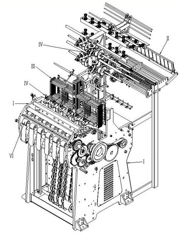
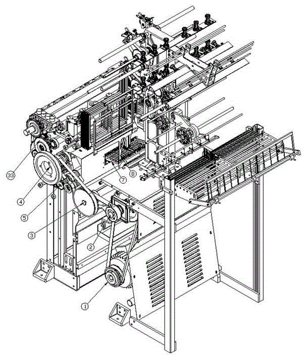
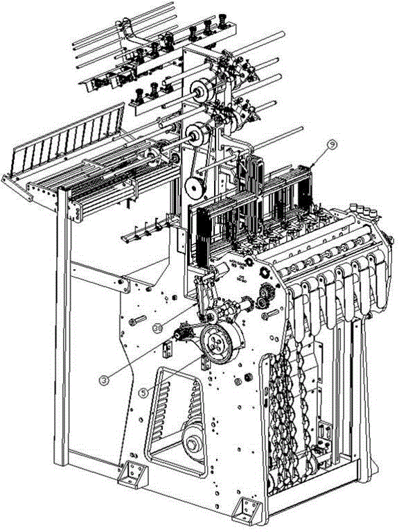
[0022] Such as figure 1 , figure 2 and image 3 As shown, a new type of high-speed flat weaving machine includes a frame on which a power mechanism, a warp feeding mechanism II, a weft yarn feeding mechanism IV, an overlock yarn feeding mechanism, an opening mechanism III, a connecting rod weaving mechanism V and The winding mechanism VI, the warp feeding mechanism II, the weft yarn feeding mechanism IV and the overlock yarn feeding mechanism constitute the yarn feeding mechanism of the ribbon loom, and the weft feeding mechanism IV includes a weft feeding variable speed shaft 10, a weft feeding umbrella wheel shaft 11, The weft-feeding umbrella wheel 12 and the belt weft-feeding device 13 installed on the weft-feeding umbrella wheel shaft 11, the overlock yarn mechanism includes a yarn-feeding axis 14, a spur gear 15, a small too...


PUM


Abstract

The invention discloses a novel high-speed flat ribbon loom which comprises a rack. A power mechanism, a warp feed mechanism, a weft feed mechanism, a catch end feed mechanism, an opening mechanism, a connecting rod weaving mechanism and a winding mechanism are arranged on the rack. The opening mechanism comprises a heald frame, a long-handled scimitar and spline pieces installed on a hub shaft. Due to the fact that wallboards of the rack are of an integrated structure, structural strength of the flat ribbon loom is improved, installation difficulty is lowered at the same time, the problem that a fault is prone to occurring due to the fact that bearing holes of the two wallboards are not concentric in a high-speed operation process is avoided, stable operation of the flat ribbon loom is guaranteed, and the service life of the shaft and bearings is prolonged; meanwhile, a transmission structure of the flat ribbon loom is redesigned, worm gear cases and a worm and gear structure with high machining and mounting difficulty are omitted, a mechanical structure is simpler and durable, and installation and maintenance cost is lower; loom body width and braid ribbon number limits are eliminated, the speed and yield of ribbons can be greatly improved, and production efficiency is improved.

Description

technical field [0001] The invention belongs to the technical field of ribbon looms, and in particular relates to a novel high-speed flat ribbon loom. Background technique [0002] The flat loom is a kind of machine used to produce some high-end garment accessories such as bra straps and high-end wrapping tapes. Taking ordinary narrow-width six looms as an example, a loom generally has six sets of weaving mechanisms arranged side by side. That is to say, one ribbon loom can weave six ribbons at the same time, and six sets of weaving working mechanisms share a set of warp yarn transmission device, weft yarn transmission device, overlock yarn transmission device and power mechanism. Existing flat looms have the following defects: one, the power mechanism adopts a worm gear structure, the casting of the turbine box is difficult, the processing difficulty and installation precision are high, the installation personnel are strictly required, the cost of the worm gear is high and ...

Claims


Application Information

Patent Timeline
IPC IPC(8): D03D35/00
Inventor 李晨
Owner 泉州众锦源精密机械有限公司
Learn More