Clamping and positioning method for friction welding of steel piston

A clamping positioning and friction welding technology, which is applied to pistons, welding equipment, non-electric welding equipment, etc., can solve the problems of the total length of the piston, the coaxiality of the head and the skirt cannot be guaranteed, the outer circle of the piston skirt is deformed, and the pin hole is 2c Extrusion deformation and other problems to achieve the effect of stable product size control, avoiding waste and avoiding deformation

Active Publication Date: 2014-10-15
DONGFENG MOTOR PARTS & COMPONENTS GROUP
View PDF5 Cites 2 Cited by
  • Summary
  • Abstract
  • Description
  • Claims
  • Application Information

AI Technical Summary

Problems solved by technology

[0005] This method clamps and locates, but because the piston skirt is a hollow shell structure, the irregular surface window structure existing on the outer circle of the piston skirt is an incomplete circumferential surface, and because the skirt wall is thin, the friction welding The clamping positioning method has the following serious problems in practical application:
[0006] (1) The rigid clamping force in the circumferential direction can easily

Method used


Image

  • Clamping and positioning method for friction welding of steel piston
  • Clamping and positioning method for friction welding of steel piston

Examples


Embodiment Construction

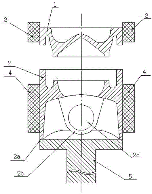
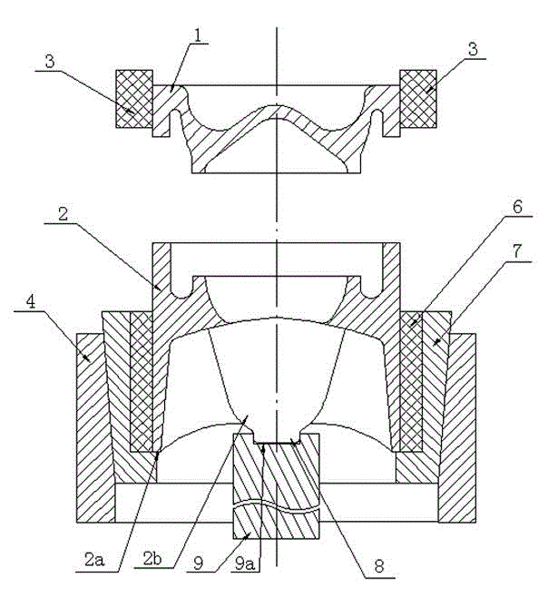
[0016] Such as figure 2 As shown, a steel piston friction welding clamping and positioning method is designed and processed with an upsetting positioning boss 8 under the pin seat 2b of the piston skirt 2, and the pin hole on the pin seat is not processed, specifically: the piston head 1 Clamp 3 the outer circle of the piston head through the first clamping block; at the other end corresponding to the friction welding equipment, the second clamping block 4 is covered with a spring collet 7 (the inner hole of the second clamping block 4 and the spring The outer circle of the jacket 7 is a taper fit), the spring jacket 7 is covered with an intermediate bush 6, the second clamping block 4 exerts force, the spring jacket 7 shrinks inward, and the piston head is clamped by the intermediate bush 6 The outer circle of the upper part, with the upsetting positioning plane 8 as the upsetting support surface, is supported by the upsetting positioning dowel 9 (the head of the upsetting p...


PUM


Abstract

The invention provides a clamping and positioning method for friction welding of a steel piston. A top forging positioning flat surface is designed and machined under a pin seat of a piston skirt part; a pin hole in the pin seat is not machined. The method comprises the concrete steps that a piston head clamps a piston head outer circle by first clamping blocks; a spring jacket is sleeved in a second clamping block at the other end corresponding to friction welding equipment; a middle bushing is sleeved in the spring jacket; the spring jacket is internally shrunk after the second clamping block applies a force; the piston head outer circle is clamped by the middle bushing; the top forging flat surface serves as a top forging support surface in the welding process and force transmission is realized by top forging positioning. The clamping and positioning method has the characteristics that a product size is stable to control, a workpiece is not deformed or damaged and the precise control on the welding quality of the product is realized.

Description

technical field [0001] The invention relates to a steel piston friction welding clamping and positioning method. Background technique [0002] In order to meet the requirement of increasing the explosion pressure of Euro V and Euro VI emission engines to above 20MPa, the traditional aluminum piston cannot meet the requirements, so steel pistons must be used. [0003] A manufacturing scheme for a steel piston with an internal cooling oil passage is to divide the piston into a piston head and a piston skirt, process the upper and lower parts of the internal cooling oil passage in advance, and weld the steel piston through friction welding. The combination of high-quality piston head and steel piston skirt forms the internal cooling oil passage of the piston. [0004] Such as figure 1 The traditional friction welding clamping method shown is as follows: the piston head 1 clamps the outer circle through the first clamping block 3; at the other end corresponding to the friction...

Claims


Application Information

Patent Timeline
IPC IPC(8): B23K20/26
CPCB23K20/126B23K2101/003
Inventor 赵敏岳济王世伟施扬陈胜奇
Owner DONGFENG MOTOR PARTS & COMPONENTS GROUP
Why Eureka
Try Eureka