Upper limb exoskeleton based on parallel driving joint

A technology of exoskeleton and joints, applied in manipulators, program-controlled manipulators, manufacturing tools, etc., can solve the problems of poor motion accuracy, small range of motion, and large size of upper limb exoskeleton robots, and achieve increased accuracy and range of motion. Effect of compactness and performance improvement

Active Publication Date: 2014-10-15
HARBIN INST OF TECH
View PDF5 Cites 19 Cited by
  • Summary
  • Abstract
  • Description
  • Claims
  • Application Information

AI Technical Summary

Problems solved by technology

[0003] In order to solve the problems of poor motion accuracy, large volume and small range of motion of existing up

Method used


Image

  • Upper limb exoskeleton based on parallel driving joint
  • Upper limb exoskeleton based on parallel driving joint
  • Upper limb exoskeleton based on parallel driving joint

Examples


specific Embodiment approach 1

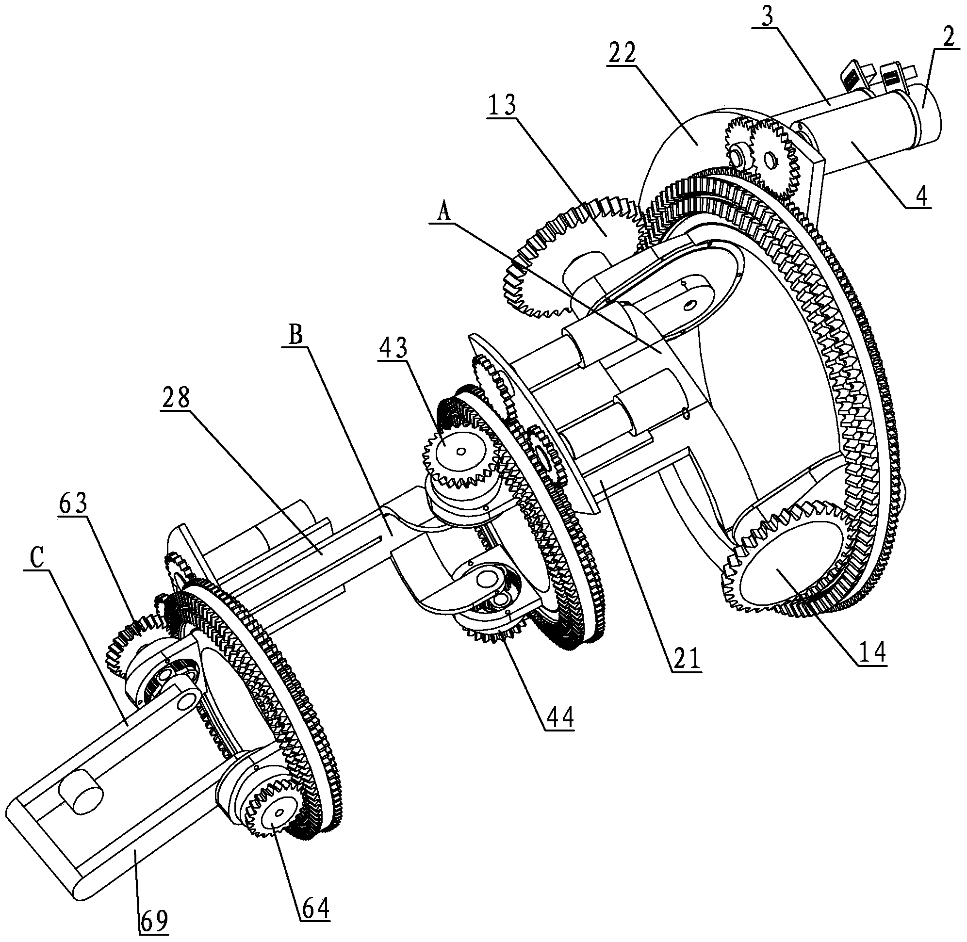
[0046] Specific implementation mode one: combine Figure 1 to Figure 18 Describe this embodiment, this embodiment includes shoulder joint A, elbow joint B and wrist joint C,

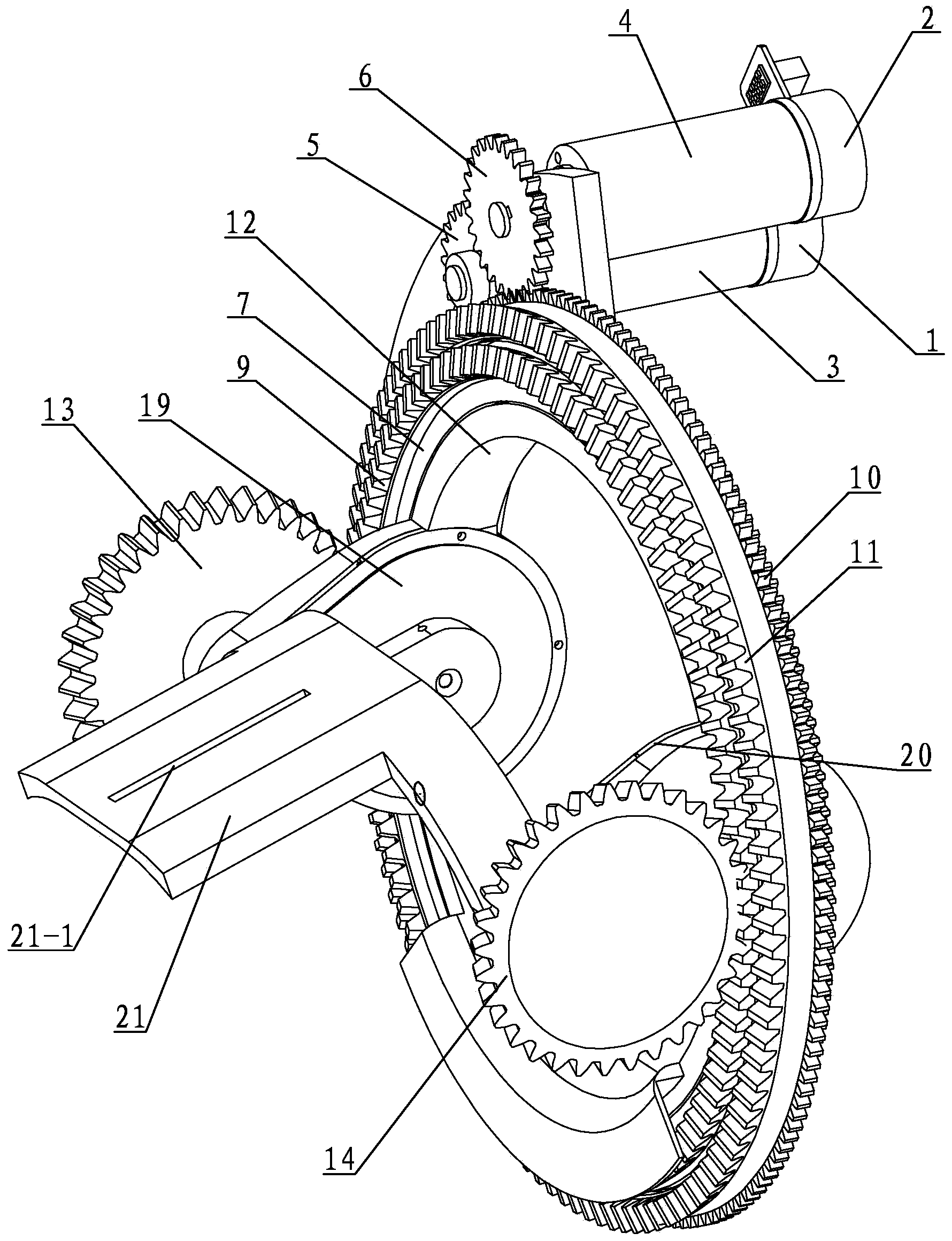
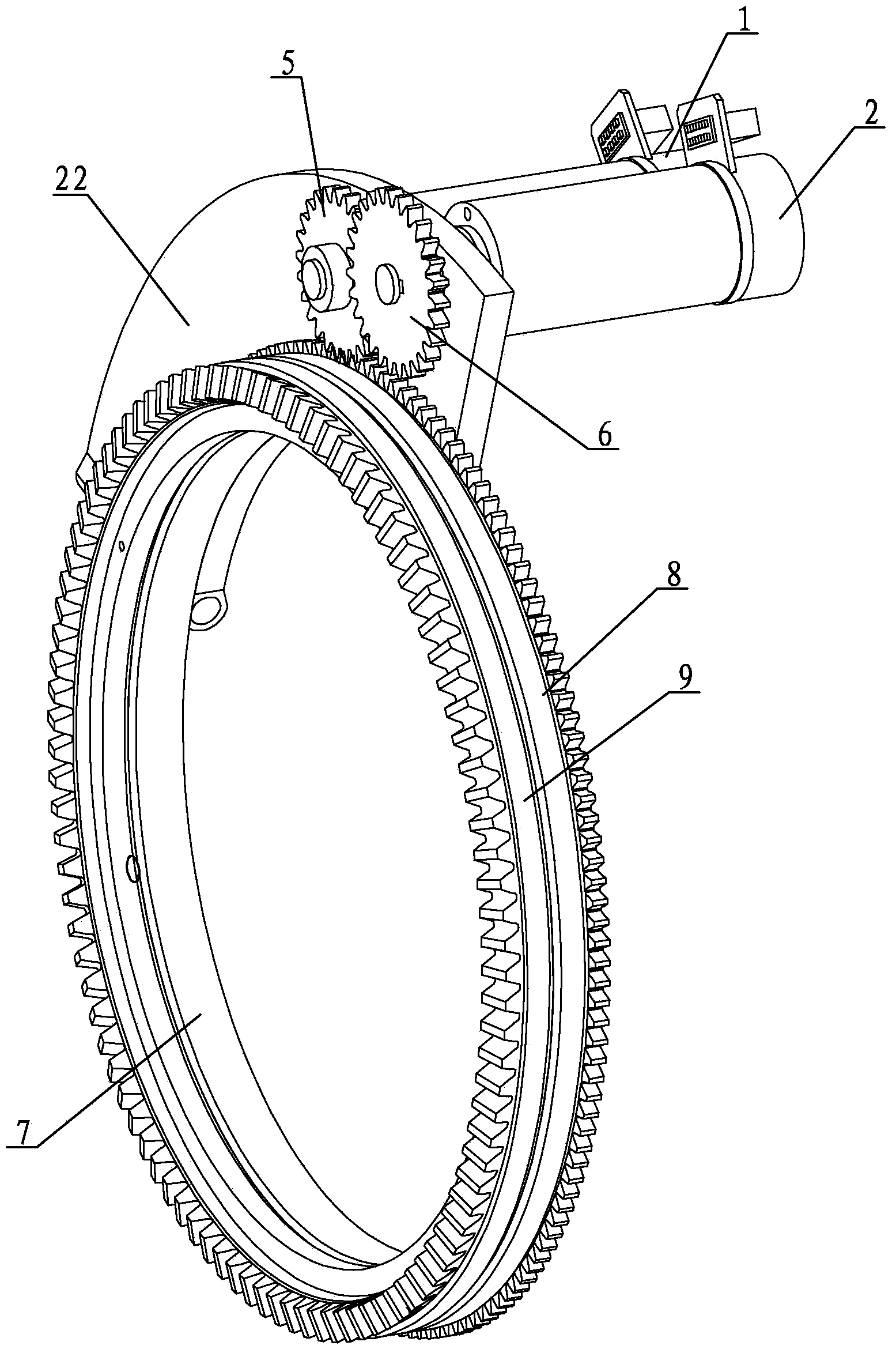
[0047] Shoulder joint A includes inner shoulder drive motor 1, shoulder outer drive motor 2, shoulder inner ring reducer 3, shoulder outer ring reducer 4, shoulder inner ring transmission gear 5, shoulder outer ring transmission gear 6, and shoulder support frame 7 , Shoulder inner ring spur gear 8, shoulder inner ring bevel gear 9, shoulder outer ring spur gear 10, shoulder outer ring bevel gear 11, shoulder driving support frame 12, shoulder left bevel gear 13, shoulder right bevel gear 14, shoulder left transmission Pinion 15, left transmission bull gear 16, right transmission bull gear 17, shoulder right transmission pinion 18, left gear box cover 19, right gear box cover 20, shoulder fixing frame 21 and shoulder support plate 22,

[0048] The shoulder support frame 7 is circular, the shoulder suppo...

specific Embodiment approach 2

[0066] Specific implementation mode two: combination image 3 , Figure 9 , Figure 10 with Figure 15 Describe the present embodiment, the shoulder support plate 22 of the present embodiment is made into one with the shoulder support frame 7, see image 3 , the elbow support plate 30, the elbow connecting plate 29 and the elbow support frame 37 are made into one, see Figure 9 with Figure 10 , wrist support plate 50, wrist connecting plate 49 and wrist support frame 57 are made into one, see Figure 15 . This is designed to increase the stability of the structure. Other components and connections are the same as those in the first embodiment.

specific Embodiment approach 3

[0067] Specific implementation mode three: combination image 3 , Figure 10 with Figure 16 Describe this embodiment, the outer diameter of the shoulder inner ring bevel gear 9 of this embodiment is the same as the outer diameter of the shoulder inner ring spur gear 8, see image 3 , the outer diameter of the elbow inner ring bevel gear 39 is the same as the outer diameter of the elbow inner ring spur gear 38, see Figure 10 , the outer diameter of the wrist inner ring bevel gear 59 is the same as the outer diameter of the wrist inner ring spur gear 58, see Figure 16 . Other compositions and connections are the same as those in Embodiment 1 or 2.


PUM


Abstract

The invention discloses an upper limb exoskeleton based on a parallel driving joint, relates to an assist robot, and aims to solve the problems of poor motion accuracy, large size and small motion range of an upper limb exoskeleton robot. The upper limb exoskeleton comprises a shoulder joint, an elbow joint and a wrist joint, wherein the shoulder joint, the elbow joint and the wrist joint are arranged in sequence; an elbow connecting plate on the elbow joint and a shoulder fixing frame on the shoulder joint are arranged one above the other; a wrist connecting plate on the wrist joint and an elbow fixing frame on the elbow joint are arranged one above the other; a second long connecting slot in the elbow connecting plate is in sliding connection with a first long connecting slot in the shoulder fixing frame; a fourth long connecting slot in the elbow connecting plate is in sliding connection with a third connecting long slot in the elbow fixing frame. The upper limb exoskeleton is applied to assistance of the aged and disabled, medical rehabilitation and the like.

Description

technical field [0001] The invention relates to an assisting robot, in particular to an upper limb exoskeleton based on parallel drive joints. Background technique [0002] At present, the exoskeleton robot can bear the load for the human body and increase the mobility of the human body. It has great application prospects in various aspects, such as military marching, earthquake rescue, and human muscle rehabilitation. However, the existing upper extremity exoskeletons Skeletal design is mostly based on serial structure design, which has poor motion accuracy, and each degree of freedom is driven by a separate motor, which makes the motor burden heavy, resulting in an increase in the size of the motor. However, the existing parallel structures are mostly in the form of connecting rod hinges, and the range of motion is also greatly limited. Contents of the invention [0003] The present invention proposes an upper limb exoskeleton based on parallel drive joints in order to ...

Claims


Application Information

Patent Timeline
IPC IPC(8): B25J17/00B25J17/02B25J9/08
Inventor 朱延河陈燕燕赵杰
Owner HARBIN INST OF TECH
Why Eureka
Try Eureka