Piston unit and hydrostatic radial piston machine

A technology of piston and hydraulic machine, applied in the field of radial piston machine and piston unit, can solve the problems of reducing starting torque, reducing efficiency, not small friction, etc., and achieving the effect of reducing manufacturing cost

Active Publication Date: 2018-09-07
ROBERT BOSCH GMBH
View PDF6 Cites 0 Cited by
  • Summary
  • Abstract
  • Description
  • Claims
  • Application Information

AI Technical Summary

Problems solved by technology

[0003] It has been shown here that such a conventional hydrostatic radial piston machine is subject to considerable friction in the region of the sliding surfaces, which friction is reduced in particular when the radial piston machine is used as a radial piston motor. required starting torque and thus reduces its efficiency

Method used


Image

  • Piston unit and hydrostatic radial piston machine
  • Piston unit and hydrostatic radial piston machine
  • Piston unit and hydrostatic radial piston machine

Examples


Embodiment Construction

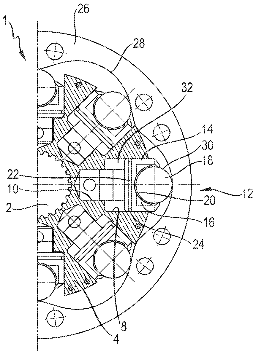
[0029] figure 1 An exemplary embodiment of the radial piston machine 1 described at the outset is shown in radial section. In the exemplary embodiment, the radial piston machine 1 is a hydrostatic radial piston motor with an external piston support.

[0030] The radial piston machine 1 has a centrally arranged shaft 2 . It is driven by a surrounding rotor 4 or a cylinder block in which a plurality of cylinders 6 are formed. In the illustrated embodiment, the radial piston machine 1 is provided with eight cylinders 6, in figure 1 Only the whole of three of them and the respective halves of the other two are shown in . The cylinders 6 are arranged radially or star-shaped around the axis 2 . Each cylinder 6 is formed by a main bore 8 and a guide bore 10 retracted radially step by step, in which a piston unit 12 is movably accommodated in the axial direction.

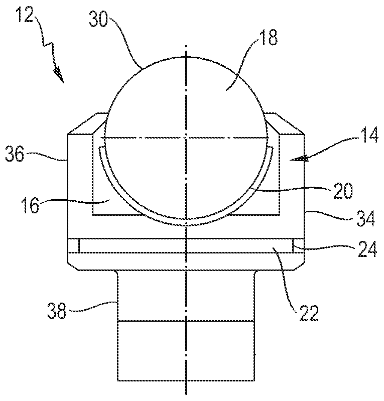
[0031] Each of the piston units 12 has a piston 14, which in the present embodiment is a multi-stage piston. At the...


PUM


Abstract

The invention discloses a piston unit and a radial piston machine designed with at least one such piston unit. According to the invention, the piston of the piston unit is polished.

Description

technical field [0001] The invention relates to a piston unit and to a hydrostatic radial piston machine having such a piston unit. Background technique [0002] A hydrostatic radial piston machine of this type, known for example from DE 40 37 455 C1, has a rotor designed as a cylinder block, in which a plurality of piston units are guided displaceably in the radial direction. Each of the piston units has a piston which is guided in the cylinder bore of the cylinder block and whose end section protrudes radially outward from the cylinder block is supported via rolling bodies in a housing forming the radial piston machine. On the stroke ring of a part of the body, the pistons are stroked according to the stroke curve on the stroke ring. [0003] It has been shown here that such a conventional hydrostatic radial piston machine is subject to substantial friction in the region of the sliding surfaces, which is reduced in particular when the radial piston machine is used as a ra...

Claims


Application Information

Patent Timeline
Patent Type & Authority Patents(China)
IPC IPC(8): F04B1/04F04B53/14F01B13/06F03C1/04
CPCF01B1/0603F16J1/02
Inventor S.史密斯G.克莫德A.G.麦金托什
Owner ROBERT BOSCH GMBH
Why Eureka
Try Eureka