
Optical distance measuring apparatus

一种光学测距、光量的技术,应用在测量装置、无线电波测量系统、仪器等方向,能够解决距离检测误差等问题

Active Publication Date: 2014-10-15
MAXELL HLDG LTD
View PDF5 Cites 14 Cited by
  • Summary
  • Abstract
  • Description
  • Claims
  • Application Information

AI Technical Summary

Problems solved by technology

[0003] APD is a photodiode that uses a phenomenon called avalanche multiplication to increase the light receiving sensitivity, but the multiplication rate will change greatly with temperature changes, and distance detection errors may occur.

Method used


Image

  • Optical distance measuring apparatus
  • Optical distance measuring apparatus
  • Optical distance measuring apparatus

Examples


Embodiment 1)

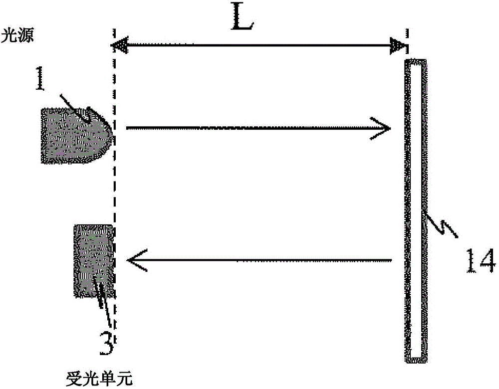
[0064] Figure 1a and Figure 1b It is a figure explaining the principle of the distance measurement of this invention. As shown in the figure, a TOF (Time of Flight) method is described that measures the difference between the emission time of light from the laser light source 1 and the light reception time of light reflected from the object 14 and received by the light receiving unit 3 . The light emitted from the laser light source 1 is irradiated onto the object 14 . The light irradiated on the object 14 is scattered, and part of the light is detected by the light receiving unit 3 . Let the time difference be t[s], then according to the speed of light 3.0×10 8 [m], the distance L[m] is expressed as:

[0065] L[m]=light speed 3.0×10 8 [m]×t[s] / 2 (1).

[0066] The distance calculation is carried out by the above formula to realize the optical distance measuring device.

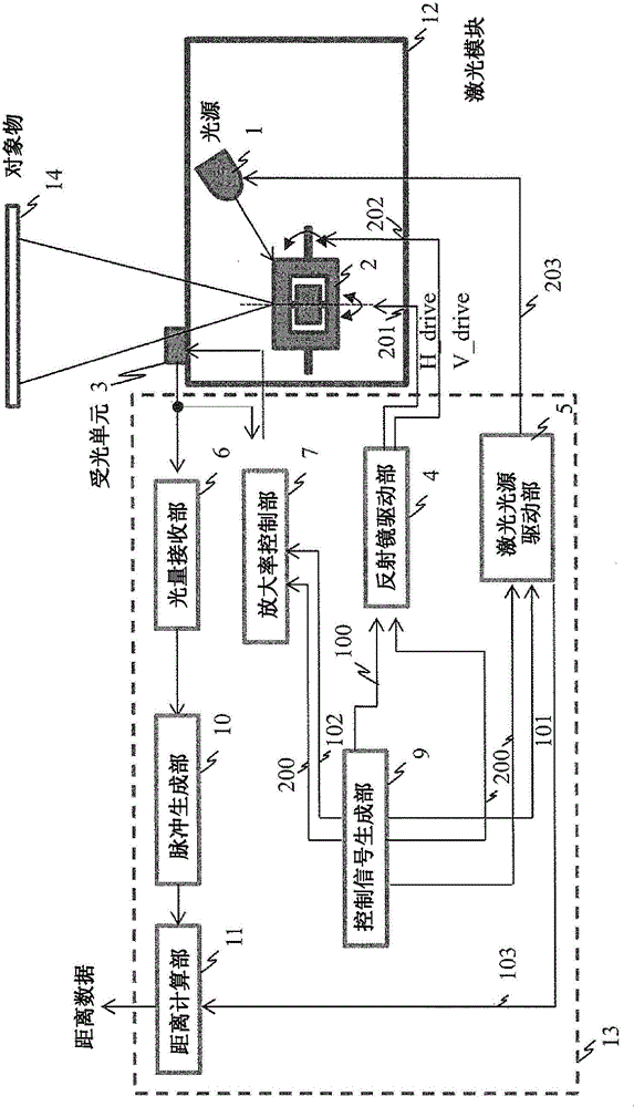
[0067] Next, use figure 2 The structure of the optical distance measuring device and its driving ...

Embodiment 2)

[0103] use Figure 12 A second embodiment of the present invention will be described. This embodiment is different from the first embodiment, the intensity of the light source 1 is controlled, and the light receiving level of the light receiving unit 3 is adjusted.

[0104] Figure 12It is a figure which shows the structure of Example 2. The difference from the first embodiment is that the laser intensity control signal 104 , which is the output of the amplification factor control unit 7 , is input to the laser light source drive unit 5 . Use below Figure 13 The configuration of the amplification factor control unit 7 in the second embodiment will be described.

[0105] Figure 13 It is a figure which shows the structure of the amplification factor control part 7 in Example 2. The difference from Example 1 is that a laser intensity control unit 74 is added. The laser intensity control unit 74 generates a signal for operating the laser light source drive unit 5 based on...


PUM


Abstract

An optical distance measuring apparatus including a light source, a variable mirror scanning the light on an object, a receiving device receiving light from the object, a detected signal amplifying unit detecting a light receiving signal obtained by the receiving device, an amplification control unit detecting a set target value of light sensitivity of the receiving device or sets the light sensitivity based on a light quantity of reflected light, and a distance calculation unit detecting a flight time of the ranging light from a light emitting signal and calculating a distance up to the object, wherein in a first scan period, the amplification control unit detects the set target value based on a light quantity of the reflected light, and in a second scan period, the amplification control unit sets sensitivity of the receiving device to the set target value and the distance calculation unit calculates the distance.

Description

technical field [0001] The present invention relates to an optical distance measuring device for irradiating distance measuring light such as laser light on a measuring object, and receiving reflected light from the measuring object to measure the distance between the object and the object. In particular, it relates to a light receiving circuit structure and a distance measuring control method. Background technique [0002] Conventionally, the TOF (Time of Flight, Time of Flight) method of distance measurement is known as one of the distance measurement methods. It adopts a structure that irradiates a distance measurement object with laser light and receives reflected light from the laser light from the object. By calculating The distance to the object (the distance between the distance measuring device and the object) is obtained by taking the time difference between the irradiation time of the laser light and the light reception time of the reflected laser light. In such a...

Claims


Application Information

Patent Timeline
Patent Type & Authority Applications(China)
IPC IPC(8): G01S17/08
CPCG01S17/08G01S7/4808G01S7/4868G01S17/42G01S7/497
Inventor 山本将史瀬尾欣穗
Owner MAXELL HLDG LTD
Learn More