On-production-line filament-arranging glass core-cutting lamp tube sealing process and dedicated sealing machine

A sealing machine and lamp technology, which is applied in the direction of electric tube/lamp closing, etc., can solve the problems of thermal stress, cold explosion, slow temperature rise, etc., and achieves the effect of eliminating the occurrence mechanism of cold explosion and solving the problem thoroughly.

Inactive Publication Date: 2014-10-15
JIANGSHAN YOUHE MACHINERY
View PDF7 Cites 8 Cited by
  • Summary
  • Abstract
  • Description
  • Claims
  • Application Information

AI Technical Summary

Problems solved by technology

In this process, because the pins have just passed the high-temperature sealing process, the pins have not cooled down. If they are installed on the glass core cutting equipment immediately, the hot pins will come into contact with the cold fixture, which will easily lead to cold burst (cold burst), Increase the breakage rate of the product. If you wait for the pins to cool down completely before processing the wire and cutting the glass core, it will take a long time and will affect the production efficiency.
[0006] In addition, in the tube clamps used in the existing lamp tube sealing equipment, the clamping surface inside the clamp arm is an ordinary circular arc surface, the radian is equivalent to the tube pins, and the clamping surfaces on both sides are combined to form an outer surface of the pins. When the tube pin is clamped, the clamped part is covered by the clamping surface. During the welding process, the high-temperature flame rapidly heats the part below the clamped part of the tube pin, and is clamped. Because the part is covered inside and will not be directly touched by the high-temperature flame, the temperature rises slowly. Finally, with the lower edge of the clamping surface as the boundary, a temperature difference is formed between the upper and lower parts, resulting in thermal stress, which is easy to cause the pin to burst.

Method used


Image

  • On-production-line filament-arranging glass core-cutting lamp tube sealing process and dedicated sealing machine
  • On-production-line filament-arranging glass core-cutting lamp tube sealing process and dedicated sealing machine
  • On-production-line filament-arranging glass core-cutting lamp tube sealing process and dedicated sealing machine

Examples


Embodiment Construction

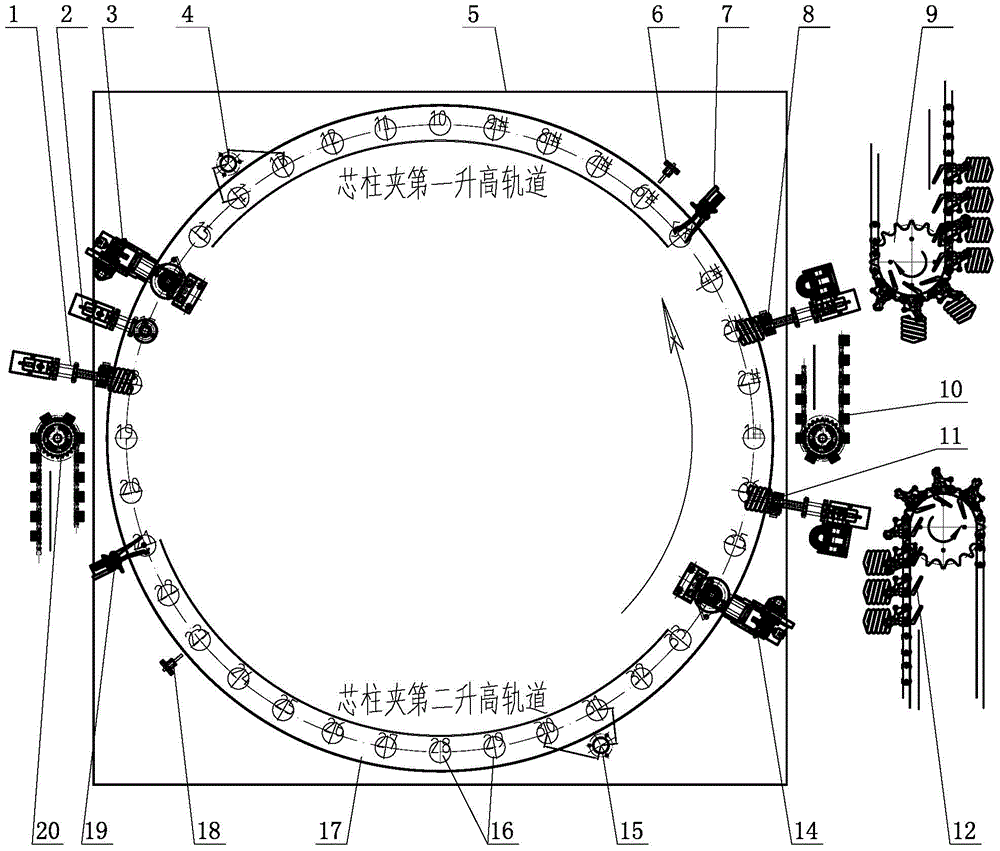
[0069] Taking a relatively specific fully automatic sealing machine designed based on the process concept of the present invention as an example, the sealing process of the present invention and the technical principle of the sealing machine for online wire trimming and cutting of glass cores will be further explained in conjunction with the accompanying drawings.

[0070] In this example, the rotary workbench 17 of the sealing machine is circular, and a plurality of stations corresponding to each process are arranged in turn along the circumference. The frame 5 rotates in one direction, so as to avoid repeated continuous sealing process.

[0071] The rotation of the worktable is usually realized by the frame, the worm gear box, and the center plate. The worm gear box is installed on the frame, and the worm gear box drives the center plate. The rotating platform is set on the center plate and rotates with the center plate. The prime mover of the worm gear box It can be a contr...


PUM


Abstract

The invention belongs to the technical field of energy-saving lamps, and discloses an on-production-line filament-arranging glass core-cutting lamp tube sealing process and a dedicated sealing machine. The process enables the processes of filament-arranging, glass core-cutting and the like to be integrated and finished on a sealing machine production line without twice tube pin clamping. The sealing machine comprises a machine frame. The machine frame is provided with a workbench. The workbench is provided with a station clamp for clamping a lamp tube and a glass core column. When the workbench is rotating, the station clamp on the bench passes a tube-feeding station, twice sealing stations, a filament-arranging and filament-separating station, a glass core-cutting station, pin-changing station and tube-taking off station and the like successively. According to the sealing machine, the filament-arranging station and the glass core-cutting station and the like are arranged between the tube-feeding station and the tube-taking off station based on the process conception. Therefore, the problem of tube pin cold explosion due to twice tube pin clamping after sealing is effectively solved.

Description

technical field [0001] The invention belongs to the technical field of energy-saving lamps, and relates to the manufacturing and processing technology of energy-saving lamp tubes, in particular to a lamp tube sealing process and a sealing machine for implementing the process. Background technique [0002] The processing of spiral energy-saving lamp tubes mainly includes several major processes such as pipe bending, bending and cutting, powder coating, powder rubbing, tube baking, sealing, exhaust, and seasoning. The sealing process is one of the major processes of energy-saving lamp tube processing. A process with high difficulty and high technical requirements. The traditional sealing process is mainly completed by the operator manually. First, the stem head of the glass stem (the filament is provided on the stem head, and the conductive wire used to connect the filament and the external power supply from the The stem cap goes out) and is vertically placed in the special to...

Claims


Application Information

Patent Timeline
Patent Type & Authority Applications(China)
IPC IPC(8): H01J9/40
Inventor 周会晶夏小均钱建春
Owner JIANGSHAN YOUHE MACHINERY
Why Eureka
Try Eureka