On-chip transformer
An on-chip transformer and main coil technology, applied in transformers, fixed transformers, electric solid devices, etc., can solve the problems of high loss and low coupling coefficient of on-chip transformers, and achieve the effect of reducing loss, uniform induced current and improving performance.
- Summary
- Abstract
- Description
- Claims
- Application Information
AI Technical Summary
Problems solved by technology
Method used
Image
Examples
Embodiment 1
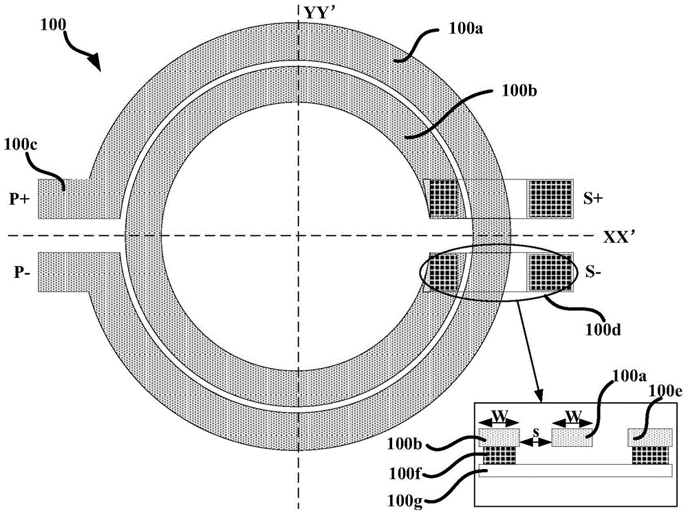
[0046] Such as Figure 2a The shown single-layer on-chip transformer 200, 200 is composed of a primary coil 200a, a secondary coil 200b, a primary coil connector 200c, and a secondary coil connector 200d, wherein the primary coil 200a is composed of two equal-width primary and secondary metal coils 200e and 200f connected in parallel, and the secondary coil 200b It consists of two equal-width secondary metal coils 200g and 200h connected in parallel. The basic dimensions of the single-layer on-chip transformer 200 are as follows: the number of primary (secondary) coils N=1, the ratio of the number of primary and secondary coils is 1:1, the width W of the primary coil and the secondary coil is both 20 μm, the width s of the annular dividing groove is 1 μm, The number of sub-coils n is 2, and the width of the sub-coils is w 1 =w 2 = 9.5 μm. Similar to the on-chip transformer 100, in order to avoid the short circuit of the primary and secondary coils, it is necessary to use th...
Embodiment 2
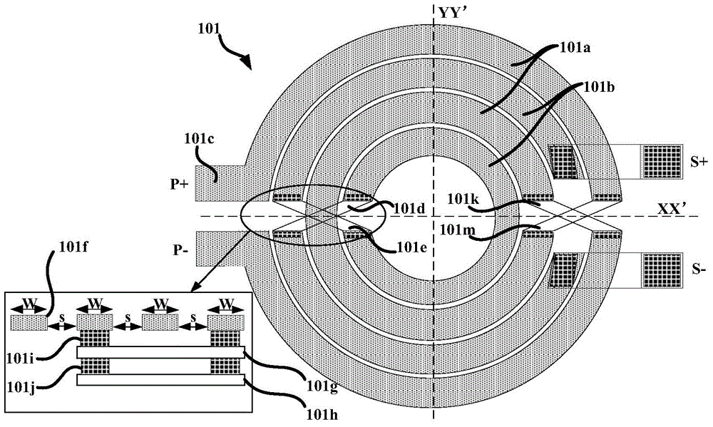
[0048] Such as Figure 3a The illustrated single-layer on-chip transformer 300, 300 consists of a primary winding 300a, a secondary winding 300b, a primary winding connection 300c, and a secondary winding connection 300d. The basic size of the on-chip transformer 300 is similar to that of Embodiment 1, the difference is that the number of sub-coils is 3, and the width of the sub-coils is w 1 =w 2 =w 3 = 6 μm. Comparison of the simulation results of the on-chip transformer 300 and the same structure of the on-chip transformer 100 designed in the prior art Figure 3b As shown, it can be seen that the coupling coefficient of the on-chip transformer 300 is higher than that of the on-chip transformer 100 within the frequency range of 0.8GHz˜10GHz.
Embodiment 3
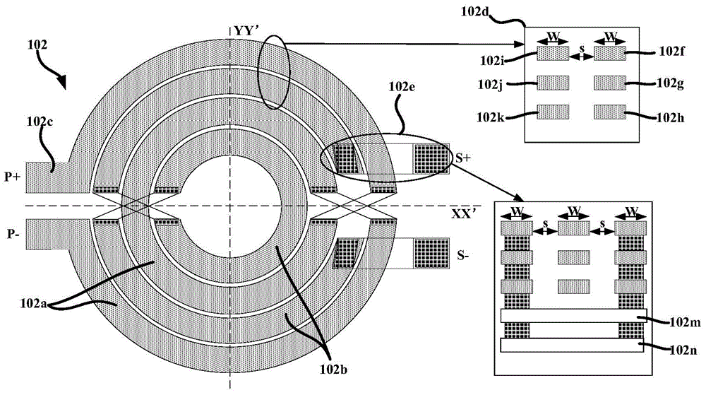
[0050] Such as Figure 4a The illustrated single-layer on-chip transformer 400, 400 consists of a primary winding 400a, a secondary winding 400b, a primary winding connection 400c, and a secondary winding connection 400d. The basic size of the on-chip transformer 400 is similar to Embodiment 1, the difference is that the number of primary (secondary) sub-coils is 4, and the width of the primary (secondary) sub-coils is w 1 =w 2 =w 3 =w 4 = 4.25 μm. Comparison of the simulation results of the single-layer on-chip transformer 400 and the on-chip transformer 100 with the same structure designed in the prior art Figure 4b As shown, it can be seen that the coupling coefficient of the single-layer on-chip transformer 400 is higher than that of the on-chip transformer 100 within the frequency range of 1.5 GHz to 10 GHz.
[0051] The above three embodiments are mainly designed from different numbers N of primary (secondary) sub-coils.
PUM
| Property | Measurement | Unit |
|---|---|---|
| thickness | aaaaa | aaaaa |
Abstract
Description
Claims
Application Information
 - R&D
- Intellectual Property
- Life Sciences
- Materials
- Tech Scout
- Unparalleled Data Quality
- Higher Quality Content
- 60% Fewer Hallucinations
Browse by: Latest US Patents, China's latest patents, Technical Efficacy Thesaurus, Application Domain, Technology Topic, Popular Technical Reports.
© 2025 PatSnap. All rights reserved.Legal|Privacy policy|Modern Slavery Act Transparency Statement|Sitemap|About US| Contact US: help@patsnap.com


