Lithium rechargeable cell with reference electrode for state of health monitoring
A reference electrode, lithium-ion battery technology, applied in the direction of secondary battery charging/discharging, small-sized battery/battery pack, secondary battery, etc., can solve the problems of insufficient stability, life, discomfort, etc.
- Summary
- Abstract
- Description
- Claims
- Application Information
AI Technical Summary
Problems solved by technology
Method used
Image
Examples
example 1
[0129] Example 1. Li-ion prismatic cell using a Li reference electrode
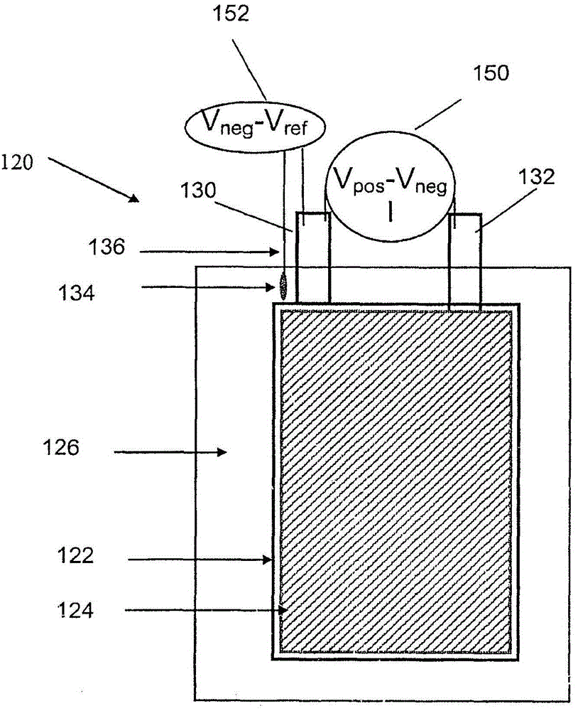
[0130] Such as Figure 5 As shown, a prismatic cell is made by stacking a negative electrode 522 , a separator 526 , and a positive electrode 524 . Copper wire 536 , which is insulated except at the end, is placed adjacent to (but not in electrical contact with) negative electrode 522 so that it is covered by separator 526 but not between the active regions of anode 530 and cathode 532 . Lithium metal 534 is then crimped over the exposed end of the copper wire. The battery is filled with electrolyte (LiPF in carbonate solvent mixture 6 ) and be sealed. The cells were subjected to a number of conditioning cycles at room temperature, then placed in a Tenney temperature chamber and brought to -20°C. Batteries were cycled on an Arbin battery cycle. Figure 6The voltage curves of such a battery during charging from a 50% state of charge at different charging rates (0.3C, 0.5C, 0.7C, 1C and 1.5C) and then ...
example 2
[0132] Example 2. Using Li 4 Ti 5 o 12 (LTO) Li-ion prismatic cells with reference electrodes
[0133] Example A: By coating an area of a piece of copper foil with Li 4 Ti 5 o 12 (LTO) paste, binder and conductive additives, then allow the paste to dry, date the application, and cut the foil into narrow strips, apply LTO to one end of each strip, thereby making a reference electrode . The uncoated portion of the copper strip is insulated with tape to create a barrier to electrolyte contact. The prismatic cell was assembled as described in Example 1 with the additional step of placing a fourth electrode on top of the separator covering the LTO reference electrode, the fourth electrode being made of a lithium-ion phosphate patch. Constructed of Al foil, sized to match the LTO reference electrode. After the cell is filled with electrolyte and sealed, current flows through the auxiliary lithium-ion phosphate electrode and the LTO reference electrode to activate the LTO r...
example 3
[0137] Example 3. Cylindrical battery using the battery can as the reference electrode terminal
[0138] Such as Figure 7 As shown, a cylindrical battery is fabricated by winding multiple repeating units of negative electrode, separator, and positive electrode.
[0139] An exemplary lithium ion battery includes a battery element having a cathode and an anode separated by a microporous separator wound closely together and disposed in a battery can. A typical spiral electrode secondary battery is Figure 7 shown in . The secondary battery 715 includes an anode sheet 701 including an anode material coated on both sides of an anode current collector; a separator 702; and a cathode sheet 703 including a cathode material coated on both sides of a cathode current collector, The anode sheet 701 , the separator 702 and the cathode sheet 703 have been stacked in the order described above and wound to form a spiral shape 709 . The cathode sheet 703 includes a current collector lead ...
PUM
| Property | Measurement | Unit |
|---|---|---|
| thickness | aaaaa | aaaaa |
Abstract
Description
Claims
Application Information
 - R&D
- Intellectual Property
- Life Sciences
- Materials
- Tech Scout
- Unparalleled Data Quality
- Higher Quality Content
- 60% Fewer Hallucinations
Browse by: Latest US Patents, China's latest patents, Technical Efficacy Thesaurus, Application Domain, Technology Topic, Popular Technical Reports.
© 2025 PatSnap. All rights reserved.Legal|Privacy policy|Modern Slavery Act Transparency Statement|Sitemap|About US| Contact US: help@patsnap.com


