Fabric swaying device of fabric dyeing machine

A cloth dyeing machine and dyeing machine technology, applied in the direction of processing textile material carrier, liquid/gas/steam jet propulsion fabric, folded textile material preservation, etc., can solve the problem of unfavorable cloth guiding, increase of production cost, and inability to centrally blow and disperse cloth And other problems, to achieve the effect of good expansion efficiency and prevent cloth entanglement

Active Publication Date: 2014-10-22
FONGS NAT ENG (SHENZHEN) CO LTD
View PDF5 Cites 10 Cited by
  • Summary
  • Abstract
  • Description
  • Claims
  • Application Information

AI Technical Summary

Problems solved by technology

However, there are many hidden dangers in this two-way pendulum design, for example, the pendulum bucket does not completely match the tail of the nozzle, but covers the tail of the nozzle with a very large shell that is larger than the cross-section of the tail of the nozzle. There are a lot of gaps between them, which take up a lot of space to avoid the collision between the two, and it is not conducive to guiding the cloth
Because the gap between the nozzle and the swing bucket is prone to pressure leakage, the air cannot be concentrated to blow and disperse the cloth, and the tail of the nozzle needs to be folded into an arc-shaped outlet in accordance with the design of the swing bucket, which also...

Method used


Image

  • Fabric swaying device of fabric dyeing machine
  • Fabric swaying device of fabric dyeing machine
  • Fabric swaying device of fabric dyeing machine

Examples


Embodiment Construction

[0049] By following embodiment, and in conjunction with accompanying drawing, the present invention is further elaborated:

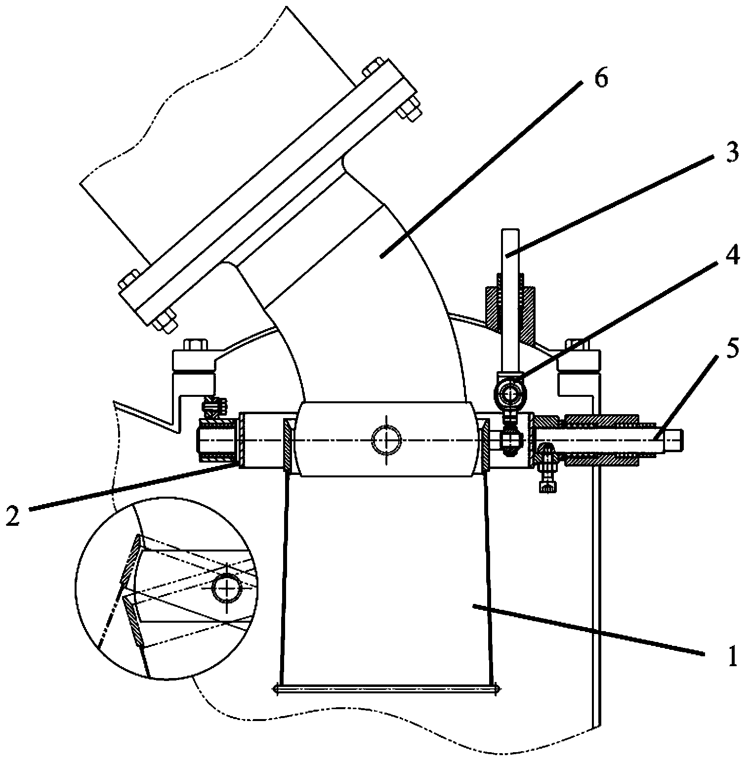
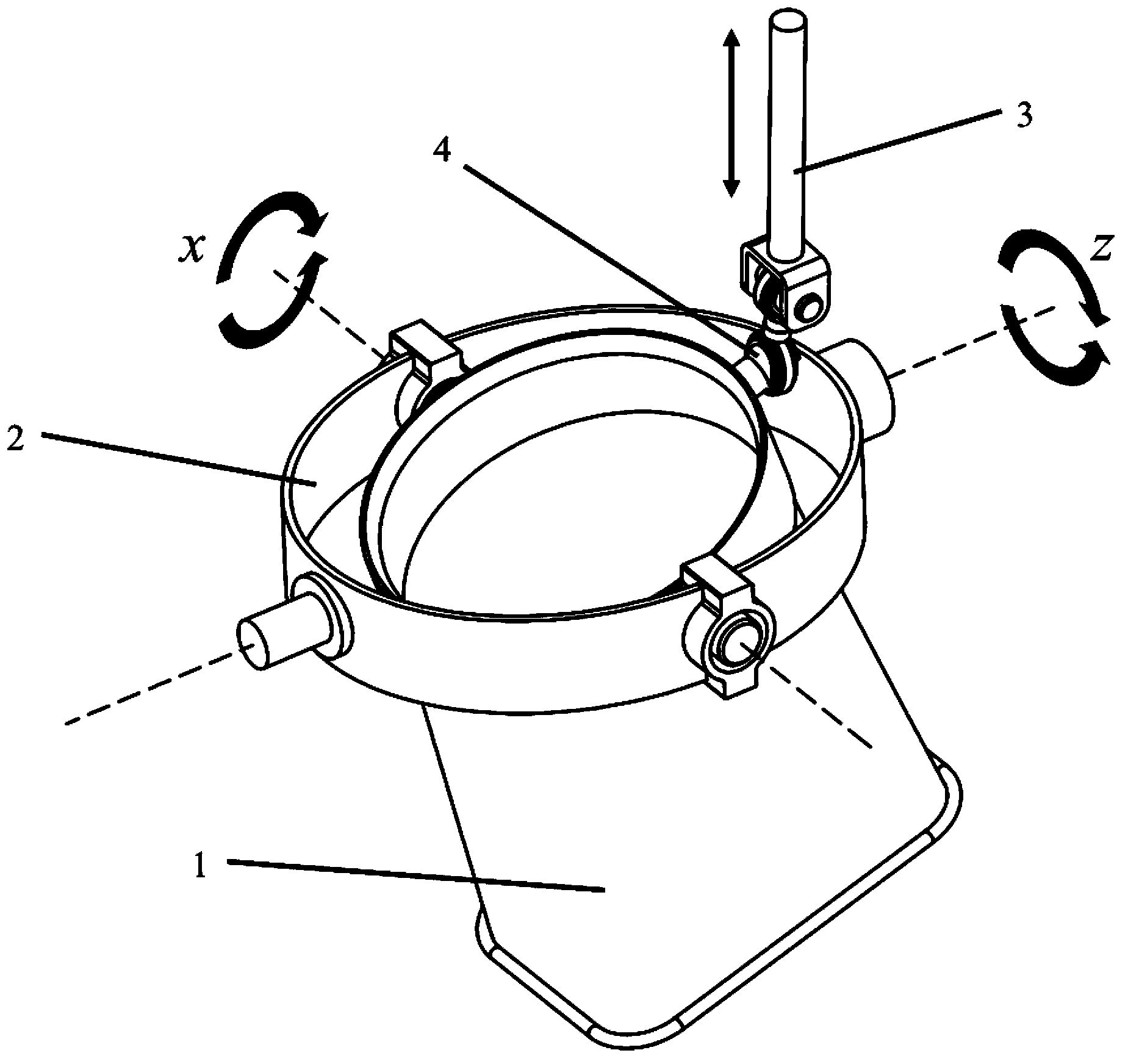
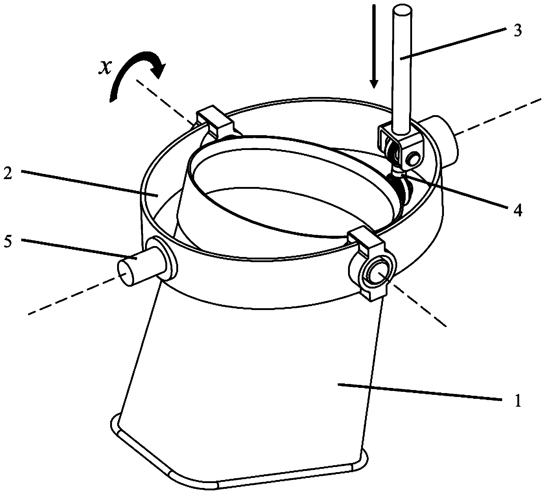
[0050] exist figure 1 , shows the cross-sectional view of the tail of the nozzle of the cloth dyeing machine according to the embodiment of the present invention. The periphery of the tail of the cloth guide pipe 6 is arc-shaped, so that the top of the left and right bucket 1 can be wrapped and rotated around its periphery, such as figure 1As shown in the circle in the lower left corner, two arbitrary positions (solid line and single dotted line) of the control bucket 1 are respectively shown when it rotates on one of the axes. The left and right bucket 1 is connected with the support ring 2 and the ball joint 4 . The supporting ring 2 is connected with the bracket in the dyeing machine, and can form an axial swing relative to the dyeing machine. The support ring is connected to the rotating shaft 5 on the above-mentioned one swinging shaft, and the r...


PUM


Abstract

The invention discloses a fabric swaying device of a fabric dyeing machine. The fabric swaying device comprises fabric guide tubes of the dyeing machine, fabric swaying hoppers, a motor, cylinders and support rings. Shaft sleeves and rotary shafts are arranged on the support rings, the support rings are connected with the fabric swaying hoppers by shafts, and the fabric swaying hoppers are connected with pistons by ball chain devices. The rotary shafts are connected with rockers and are further connected with the motor by four-bar linkage structures, and the four-bar linkage structures comprise connecting bars and cranks. The pistons are connected with plungers of the cylinders. Pneumatic control and the motor can be operated by the aid of an electronic control system. The outer wall of the tail of each fabric guide tube is in the shape of a spherical surface, the circular top of each fabric swaying hopper covers the tail of the corresponding fabric guide tube, and various positions of the top of each fabric swaying hopper can closely cling to the corresponding fabric guide tube during swaying. The fabric swaying device can be provided with the multiple four-bar linkage structures, and each four-bar linkage structure is connected with the corresponding fabric swaying hopper. The fabric swaying device has the advantage that the fabric swaying device can be widely applied to the industry of printing and dyeing machinery.

Description

technical field [0001] The invention relates to a printing and dyeing equipment, in particular to an arranging device for a cloth dyeing machine. Background technique [0002] The existing cloth dyeing machines all include structures such as nozzles and cloth storage tanks, so that the cloth circulates in the cloth dyeing machine in a continuous rope-like manner. The cloth falls into the cloth storage tank after passing through the nozzle, and the cloth storage tank is generally wider than the outlet of the nozzle. In order to avoid the disorderly stacking of the cloth falling into the cloth tank, a common method is to adopt a one-way pendulum-type cloth drop method, and the connection can swing The sleeve is at the tail of the nozzle, so that the cloth falling into the cloth groove can be folded and placed in the cloth groove according to the swing of the sleeve. [0003] However, the one-way pendulum-type cloth drop method is not conducive to the cloth being stacked in th...

Claims


Application Information

Patent Timeline
IPC IPC(8): D06B23/04
CPCD06B3/28D06B17/02
Inventor 徐达明
Owner FONGS NAT ENG (SHENZHEN) CO LTD
Why Eureka
Try Eureka