
led aircraft landing light

A technology of aircraft landing lights and LED modules, which is applied in the field of LED lighting, can solve the problems of short working life, poor lighting effect of light sources, and waste of airborne energy, so as to reduce maintenance costs, prevent visual fatigue, and improve visual senses

Active Publication Date: 2016-08-17
Anhui Huaxia Photoelectrics Co Ltd
View PDF6 Cites 0 Cited by
  • Summary
  • Abstract
  • Description
  • Claims
  • Application Information

AI Technical Summary

Problems solved by technology

[0003] 1. Poor lighting effect
The color temperature of incandescent lamps is about 3000K, so the light color of incandescent landing lights is obviously yellowish, the lighting effect of the light source is poor, and it is easy to cause visual fatigue
[0004] 2. High power consumption
The light efficiency of incandescent lamps is very low. In order to meet the requirements of technical indicators, the power of incandescent landing lights is very large. The smallest landing lights have a power of 450W, and some models even need 1000W to meet the use requirements.
[0005] 3. Short life
Airborne lighting is powered by DC 28V system, and the power of incandescent landing lights is very large, so its working current must reach tens of amps, resulting in a very short working life, generally only tens of hours
[0006] 4. Poor anti-vibration performance
[0007] To sum up, as a traditional incandescent lamp that has been used for a hundred years, continuing to use it as an aircraft landing light not only wastes precious airborne energy, but also has a short life, cumbersome maintenance, and low structural safety and reliability.

Method used


Image

  • led aircraft landing light
  • led aircraft landing light
  • led aircraft landing light

Examples


Embodiment Construction

[0033] Referring to the accompanying drawings, through the description of the embodiments, the specific implementation of the present invention, such as the shape, structure, mutual position and connection relationship between the various parts, the function and working principle of each part, and the manufacturing process And the method of operation and use, etc., are described in further detail to help those skilled in the art have a more complete, accurate and in-depth understanding of the inventive concept and technical solution of the present invention.

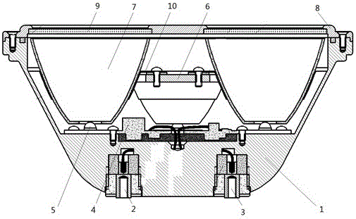
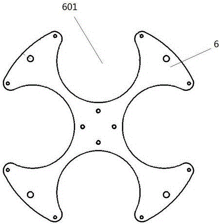
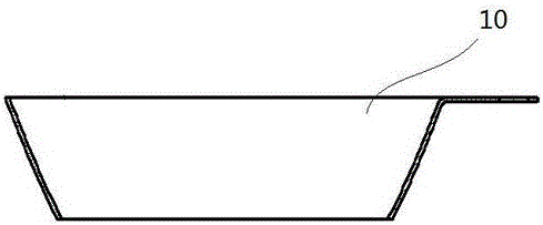
[0034] Such as figure 1 As shown, the LED aircraft landing light of the present invention is mainly composed of a main body shell 1, a positive connector 2, a negative connector 3, a drive module 4, an LED module 5, a light cup holder 6, a reflector 7, a front cover 8, and a glass slide 9 and so on. Some of the above components need to be fixedly connected by screws, gaskets, etc., and the circuit components need to be ...


PUM


Abstract

The invention discloses an LED aircraft landing light, which comprises a main body shell, a drive module, an LED module, a light cup fixing frame, a light reflection cup, a front cover and a glass slide. The invention has a long working life and greatly reduces the maintenance cost in the later stage; there is no filament breakage problem of the traditional landing light, and it is more suitable for the requirements of the airborne environment; the power consumption can be reduced to about one-fifth of the traditional landing light; It improves the pilot's visual sense and is not easy to cause visual fatigue; it can be directly installed on the landing lamp of the existing aircraft; the structure adopted by it has good heat dissipation effect, convenient installation, compact structure, reliable position of reflector and LED module after installation, and good working effect it is good.

Description

technical field [0001] The invention belongs to the field of LED lighting, in particular to an LED aircraft landing light. Background technique [0002] Aircraft landing lights are an essential external lighting source for every aircraft. Traditional landing lights are all incandescent lamps with tungsten wicks. Although they have the advantages of mature technology and low price, their shortcomings are also obvious, as follows: [0003] 1. The lighting effect is poor. The color temperature of incandescent lamps is about 3000K, so the light color of incandescent landing lights is obviously yellowish, the lighting effect of the light source is poor, and it is easy to cause visual fatigue. [0004] 2. High power consumption. The light efficiency of incandescent lamps is very low. In order to meet the requirements of technical indicators, the power of incandescent landing lights is very high. The smallest landing lights have a power of 450W, and some models even need 1000W t...

Claims


Application Information

Patent Timeline
Patent Type & Authority Patents(China)
IPC IPC(8): F21S8/00F21V17/10F21V23/00F21W101/06F21Y115/10F21W107/30
Inventor 胡海城毕竞罗菲张娟吴晨
Owner Anhui Huaxia Photoelectrics Co Ltd
Learn More