
Automatic-positioning vibration sampler

An automatic positioning and sampling machine technology, which is applied in the field of sampling machines, can solve the problems of poor mixing effect, large space occupation, and high cost, and achieve the effects of improving sampling accuracy, reducing equipment weight, and saving material costs

Active Publication Date: 2014-10-22
SUZHOU RIHE TECH
View PDF7 Cites 5 Cited by
  • Summary
  • Abstract
  • Description
  • Claims
  • Application Information

AI Technical Summary

Problems solved by technology

Since the sampling mechanism and the stirring mechanism are separated, the layout is not concise enough, the space is larger, the more devices, the higher the cost, and the greater the probability of failure; at the same time, for the multi-tube sampling mechanism, due to The caliber of the test tube used is relatively narrow, and the stirring mechanism cannot be added when extracting the liquid to be tested, resulting in inaccurate detected data. In view of the above technical problems, the prior art also proposes a vibrating plate with left and right swings, the vibrating plate Connected with the sampling needle, the vibrating plate drives the sampling needle to swing left and right or back and forth, the swing direction is single, the stirring effect is not good, and the swing range is not easy to control, that is, the sampling needle is easy to touch the inner wall of the test tube during the swing process, and even Destruction of test tubes and sampling needles

Method used


Image

  • Automatic-positioning vibration sampler
  • Automatic-positioning vibration sampler
  • Automatic-positioning vibration sampler

Examples


Embodiment Construction

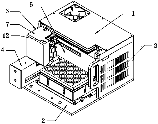
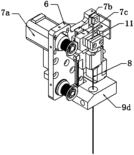
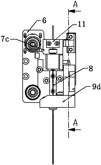
[0026] Example: refer to Figures 1 to 6 As shown, an automatic positioning vibrating sampling machine includes upper and lower fixing plates 1, 2, a support plate 3 that is used to connect and fix and is vertically arranged with the upper and lower fixing plates 1, 2, and is located on the lower fixing plate 2. X-direction drive mechanism 4, Y-direction drive mechanism 5 connected with X-direction drive mechanism 4, Z-direction drive mechanism 7 connected with Y-direction drive mechanism 5 through longitudinal fixing seat 6, sampling needle 8 connected with Z-direction drive mechanism 7 , and the sampling needle vibration mechanism, the sampling needle vibration mechanism includes a vibration motor 9a fixed on the longitudinal fixed seat 6, an eccentric wheel device 9b connected to the output end of the vibration motor 9a, and a vibration device connected to the eccentric wheel device 9b through a connector 9c plate 9d, one end of the sampling needle 8 passes through the vi...


PUM


Abstract

The invention discloses an automatic-positioning vibration sampler. The automatic-positioning vibration sampler comprises an upper fixing plate, a lower fixing plate, a support plate which is used for connection fixing and is perpendicular to the upper fixing plate and the lower fixing plate, a X-direction driving mechanism arranged on the lower fixing plate, a Y-direction driving mechanism connected to the X-direction driving mechanism, a Z-direction driving mechanism connected to the Y-direction driving mechanism by a longitudinal fixing base and a sampling pin connected to the Z-direction driving mechanism. The automatic-positioning vibration sampler also comprises a sampling pin vibrating mechanism. The sampling pin vibrating mechanism comprises a vibrating motor fixed to the longitudinal fixing base, an eccentric wheel device connected to an output end of the vibrating motor and a vibrating plate connected to the eccentric wheel device by a connection member. One end of the sampling pin goes through the vibrating plate. The eccentric wheel device in the sampling pin vibrating mechanism drives the vibrating plate to carry out eccentric motion so that the sampling pin is further driven to carry out eccentric motion to stir a liquid to be detected in a test tube and thus compared with the existing sampler, the automatic-positioning vibration sampler improves stirring effects and a sampling precision.

Description

technical field [0001] The invention relates to a sampling machine, in particular to an automatic positioning vibration sampling machine. Background technique [0002] At present, the structure and movement modes of the sampling mechanism and the stirring mechanism in the prior art are generally similar or the same, that is, the sampling mechanism and the stirring mechanism are separated, each forming a set of mechanisms, and the action process is controlled separately without interfering with each other. Since the sampling mechanism and the stirring mechanism are separated, the layout is not concise enough, the space is larger, the more devices, the higher the cost, and the greater the probability of failure; at the same time, for the multi-tube sampling mechanism, The caliber of the test tube used is relatively narrow, and the stirring mechanism cannot be added when extracting the liquid to be tested, resulting in inaccurate detected data. In view of the above technical pr...

Claims


Application Information

Patent Timeline
IPC IPC(8): G01N1/10G01N1/38
Inventor 钱澄缪海飞李藏珍
Owner SUZHOU RIHE TECH
Learn More