Eureka AIR delivers breakthrough ideas for toughest innovation challenges, trusted by R&D personnel around the world.

Wireless charging system and electric vehicle

A wireless charging, electric vehicle technology, applied in electric vehicles, electromagnetic wave systems, battery circuit devices, etc., can solve the problems of limited energy storage, affecting the cruising range of electric vehicles, etc., to achieve the effect of promoting application

Inactive Publication Date: 2014-10-22
CHERY AUTOMOBILE CO LTD
View PDF6 Cites 17 Cited by
  • Summary
  • Abstract
  • Description
  • Claims
  • Application Information

AI Technical Summary

Problems solved by technology

However, the existing supercapacitor power battery packs have limited energy storage, which seriously affects the cruising range of electric vehicles

Method used


Image

  • Wireless charging system and electric vehicle
  • Wireless charging system and electric vehicle
  • Wireless charging system and electric vehicle

Examples


Embodiment 1

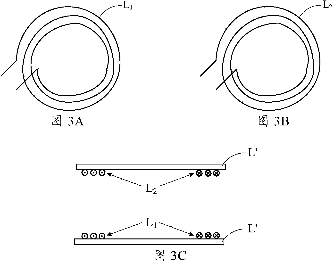
[0042] Such as figure 1 As shown, this embodiment provides a wireless charging system, which includes: a ground device 100, a ground transmitting coil L 1 , Vehicle receiving coil L 2 and the vehicle-mounted device 200 .

[0043] Wherein, the ground device 100 is connected with the power grid and the ground transmitting coil L respectively 1 Connected, used to modulate the electric energy of the grid and output it to the ground transmitting coil L 1 , so the ground device 100 can also be called a charging pile.

[0044] Preferably, the ground device modulates the electric energy in the power grid specifically as follows: converting the power-frequency AC power in the power grid into high-frequency AC power in the range of 10kHz to 200kHz, and the magnetic field generated by the high-frequency AC in this frequency range passes through the ground transmitting coil L 1 and on-board receiving coil L 2 Energy can be transmitted efficiently even when the distance is relatively...

Embodiment 2

[0055] Such as Figure 4 As shown, this embodiment provides a wireless charging system, which includes: a ground device 100, a ground transmitting coil L 1 , Vehicle receiving coil L 2 and the vehicle-mounted device 200 .

[0056] Specifically, the ground device 100 includes: a first rectifier 101, a first capacitor C 1 , the first inverter 102, the second capacitor C 2 and the first control unit 103 .

[0057] The input end of the first rectifier 101 is connected to the power grid, and the output end is connected to the first capacitor C 1 connected to both ends, used to convert the power frequency AC power in the grid into DC power and output it to the first capacitor C 1 . The first rectifier 101 can be a three-phase / single-phase rectifier compatible with the power grid.

[0058] The first capacitor C 1 Both ends of are also connected to the input end of the first inverter 102 for filtering the DC power and outputting it to the first inverter 102 .

[0059] The out...


PUM


Abstract

The invention provides a wireless charging system. The wireless charging system comprises a ground device, a ground transmitting coil, a vehicle mounted receiving coil and a vehicle mounted device. The ground device is connected with a power grid and the ground transmitting device and used for modulating and outputting electric energy of the power grid to the ground transmitting coil; the ground transmitting coil is used for transmitting the modulated electric energy in a mode of magnetic field energy; the vehicle mounted receiving coil is connected with the vehicle mounted device and used for receiving the magnetic field energy transmitted by the ground transmitting coil and outputting the magnetic field energy to the vehicle mounted device; the vehicle mounted device is used for converting the magnetic field energy received by the vehicle mounted receiving coil into electric energy and storing the electric energy to drive the motor of an electric vehicle. Correspondingly, the invention also provides the electric vehicle utilizing the wireless charging system. The wireless charging system can achieve rapid charging of the electric vehicle and meanwhile avoid influence the service range of the electric vehicle.

Description

technical field [0001] The invention relates to the technical field of vehicle charging, in particular to a wireless charging system and an electric vehicle using the wireless charging system. Background technique [0002] Compared with traditional wired charging technology, wireless charging technology (also known as wireless energy transmission technology) is especially suitable for the field of electric vehicle charging because of its advantages of safety, reliability, convenient layout, and intelligent management. However, in order to avoid damage to the vehicle power battery pack, the wireless charging technology cannot charge the vehicle power battery pack too fast. In order to improve the charging efficiency, it is necessary to equip a large number of wireless charging devices for electric vehicles. Therefore, it is not suitable for popularization and application. [0003] In order to solve the above problems, a supercapacitor power battery pack has appeared in the p...

Claims


Application Information

Patent Timeline
IPC IPC(8): H02J7/00H02J17/00H02J50/12
Inventor 张旭辉王晓辉王建辉朱得亚赵世一
Owner CHERY AUTOMOBILE CO LTD
Why Eureka
Eureka Blog
Learn More