Method and device for monitoring Ethernet clock synchronization

A clock synchronization and Ethernet technology, applied in the Internet field, can solve problems such as the inability to know the time synchronization between the clock device and the master clock device, frequent packet loss of time synchronization messages, and large time deviation between the slave clock device and the master clock device.

Active Publication Date: 2014-10-22
KYLAND TECH CO LTD +1
View PDF3 Cites 33 Cited by
  • Summary
  • Abstract
  • Description
  • Claims
  • Application Information

AI Technical Summary

Problems solved by technology

[0003] Industrial Ethernet has high requirements for clock synchronization. If there is an error in the time synchronization between the slave clock device and the master clock device, and the error cannot be detected in time, the time deviation between the slave clock device and the master clock device may become larger. Get bigger and bigger, eventually the time cannot be synchronized
[0004] In the existing 1588 clock synchronization protocol, the master clock device only periodically sends clock synchronization messages, or sends time synchronization messages according to the time synchronization request of the slave clock device, but the master clock device cannot know the difference between the slave clock device and the master clock device. Whether to perform time synchronization, or whether the time synchronization between the slave clock device and the master clock device is accurate
In addition, according to the PTP protocol, when the slave clock device receives the clock synchronization message sent by the master clock device, it adjusts the local clock by calculating the phase compensation value OFFSET, thereby achieving time synchronization with the master clock device. However, when the slave clock device When there is a problem with the hardware configuration itself, the phase compensation value OFFSET calculated by the hardware configuration is an incorrect value, so the slave clock device a

Method used


Image

  • Method and device for monitoring Ethernet clock synchronization
  • Method and device for monitoring Ethernet clock synchronization
  • Method and device for monitoring Ethernet clock synchronization

Examples


Embodiment Construction

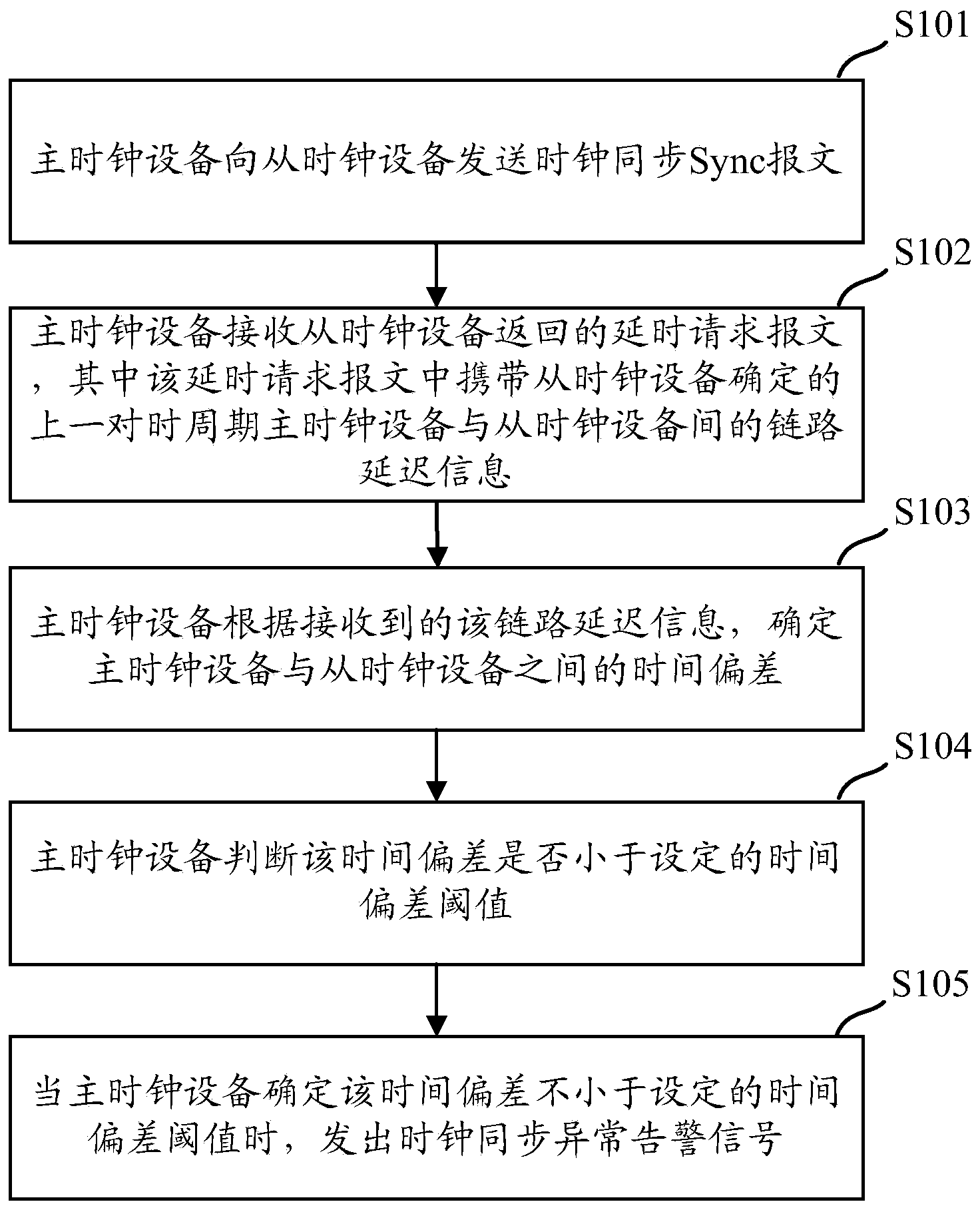
[0045] In order to effectively monitor the time synchronization of each slave clock device in the network, discover in time the synchronization anomaly between the slave clock device and the master clock device, and improve the reliability of the network, an embodiment of the present invention provides a monitoring Ethernet clock synchronization Methods and devices.

[0046] Exemplary embodiments of the present disclosure will be described in more detail below with reference to the accompanying drawings. Although exemplary embodiments of the present disclosure are shown in the drawings, it should be understood that the present disclosure may be embodied in various forms and should not be limited by the embodiments set forth herein. Rather, these embodiments are provided for more thorough understanding of the present disclosure and to fully convey the scope of the present disclosure to those skilled in the art.

[0047] Embodiments of the present invention will be described be...


PUM


Abstract

The embodiment of the invention provides a method and device for monitoring Ethernet clock synchronization. In the method, a slave clock device returns a delay request message to a master clock device, and the delay request message carries link delay information between the master clock device and the slave clock device of a last time hack cycle, determined by the slave clock device, so that the master clock device is enabled to determine a time deviation between the master clock device and the slave clock device and according to whether the time deviation is smaller than a set time deviation threshold, whether to send alarm information is determined. Because in the method, the slave clock device returns the determined link delay information between the slave clock device and the master clock device to the master clock device from the master clock device so that the master clock device is enabled to determine a time hack condition of the slave clock device so as to achieve an objective of monitoring of the slave clock device and thus precision demands of time synchronization are ensured and loss caused by inaccuracy of time hack is reduced.

Description

technical field [0001] The invention relates to the technical field of the Internet, in particular to a method and device for monitoring Ethernet clock synchronization. Background technique [0002] IEEE1588 is a precise clock synchronization protocol based on the message. It transmits messages between the master clock and the slave clock based on the PTP protocol, and can realize precise time synchronization and frequency synchronization in the packet transmission network. Among them, frequency synchronization refers to the specific relationship that the frequency or phase appears at the same average rate at the corresponding effective instant, so as to maintain all the devices in the communication network to operate at the same rate. Clock synchronization means that the frequency between the signals is the same, and they are consistent in phase. [0003] Industrial Ethernet has high requirements for clock synchronization. If there is an error in the time synchronization b...

Claims


Application Information

Patent Timeline
IPC IPC(8): H04J3/06H04L12/26
CPCH04J3/06H04L43/00
Inventor 尹二飞
Owner KYLAND TECH CO LTD
Why Eureka
Try Eureka