Image real-time correction output method for broad-width scanner

A real-time correction and output method technology, applied in the direction of image communication, electrical components, etc., can solve problems that have not yet been effectively optimized simultaneously

Inactive Publication Date: 2014-10-22
NINGBO MOSHI OPTOELECTRONICS TECH
View PDF3 Cites 15 Cited by
  • Summary
  • Abstract
  • Description
  • Claims
  • Application Information

AI Technical Summary

Problems solved by technology

[0003] Although the above two aspects are the key to solving the problem of wide-format scanners obtaining high quality while transmitting

Method used


Image

  • Image real-time correction output method for broad-width scanner
  • Image real-time correction output method for broad-width scanner
  • Image real-time correction output method for broad-width scanner

Examples


Embodiment

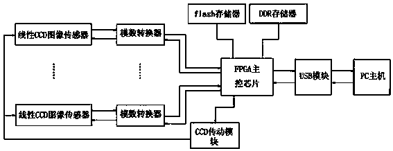
[0043] Such as figure 1As shown, the present invention is mainly applied to wide-format scanners, and its hardware is mainly provided with an FPGA main control chip with an algorithm module (i.e. hardware multiplier) and a random access memory (i.e. RAM), and the output terminals are all connected to A plurality of analog-to-digital converters connected to the input end of the FPGA main control chip, a CCD transmission module connected to the output end of the FPGA main control chip, a flash memory, a DDR memory and a USB module that are bidirectionally connected to the FPGA main control chip, and The USB module is bidirectionally connected to a PC host, and a linear CCD image sensor whose output end is connected to an input end of an analog-to-digital converter and is also connected to a CCD transmission module.

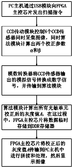
[0044] Based on the above hardware structure, such as figure 2 Shown, the realization process of the present invention is as follows:

[0045] (1) After the syst...


PUM


Abstract

The invention discloses an image real-time correction output method for a broad-width scanner. The method includes the following steps: (1) a PC host sends a scanning instruction to an FPGA main control chip; (2) the FPGA main control chip controls N linear CCD image sensors to light on at the same time and controls a CCD transmission module to control the N linear CCD sensors to acquire images synchronously and at the same time, an algorithm module in the FPGA main control chip calculates two correction parameters Alpha and Beta respectively; (3) the linear CCD sensors acquire image data and transmit the image data to analog-to-digital converters and the analog-to-digital converters convert analog signals into digital signals and transmit the digital signals to the algorithm module in the FPGA main control chip to carry out processing; (4) the algorithm module calculates gray level values corrected by all photosensitive units; (5) the FPGA main control chip transmits the gray level values corrected by the photosensitive units to the PC host for processing so as to display images. The image real-time correction output method for the broad-width scanner is reasonable in design, high in processing speed and high in imaging precision.

Description

technical field [0001] The invention relates to an image output method, in particular to an image real-time correction output method of a wide-width scanner. Background technique [0002] In recent years, due to the needs of high-resolution and ultra-wide-format inspection sites, wide-format scanners using multiple CCD (Charge Coupled Device) imaging solutions have been widely used. How to obtain high-quality scanned images while ensuring fast transmission of large-capacity image data has always been one of the most difficult problems that wide-format scanners need to solve. To solve the above problems, we need to start from the following two aspects at the same time: (1) shorten the gray scale correction time of the scanned image. Therefore, it is very necessary to correct the grayscale of the scanned image. (2) When the time-consuming image correction is no longer the bottleneck of the entire system, it is necessary to increase the speed of intermediate transmission of i...

Claims


Application Information

Patent Timeline
IPC IPC(8): H04N1/60H04N1/028
Inventor 陈仕隆张峰杨雷赵泽东吕坤
Owner NINGBO MOSHI OPTOELECTRONICS TECH
Why Eureka
Try Eureka