
Splined wheel hub and machining method thereof

A splined wheel and wheel hub technology, which is applied in the field of wheel hubs, can solve problems such as joint gaps, small force capacity, and difficulties, and achieve the effects of reliable transmission and braking, reliable use, and convenient assembly

Inactive Publication Date: 2014-10-29
JIANGSU YANGGONG POWER MACHINERY
View PDF8 Cites 5 Cited by
  • Summary
  • Abstract
  • Description
  • Claims
  • Application Information

AI Technical Summary

Problems solved by technology

This processing method cannot guarantee the concentricity of the spline in the center of the hub and the brake iron ring, which will affect the assembly of the next process and the quality of the hub
If the concentricity of the brake ring and the spline cannot be guaranteed, it will have a negative impact on assembly, wheel hub quality, braking effect, and driving safety. The cumulative error caused the brake ring and the spline to be out of axis
In order to solve the above technical problems, the splines can be coaxial with the brake iron ring by post-processing the splines. This is a relatively easy technical solution. However, after the splines are installed on the hub body, the There are difficulties in processing. One is that the keyway of the inner ring of the spline is processed axially with a broach, and before the broach is processed, the inner ring of the spline needs to be bored. During the above processing, the tool Both axial force and tangential force are generated on the spline. Generally speaking, the spline has sufficient bearing capacity in the circumferential direction, but in the axial direction, its force capacity is generally relatively small, and it is easy to generate axial displacement
[0003] In addition, during the long-term use of the hub, due to the different materials of the spline and the hub body, the long-term thermal expansion and contraction will generate large internal stress, making it easy to generate gaps at the joints, which will affect the working life of the wheel.

Method used


Image

  • Splined wheel hub and machining method thereof
  • Splined wheel hub and machining method thereof
  • Splined wheel hub and machining method thereof

Examples


Embodiment Construction

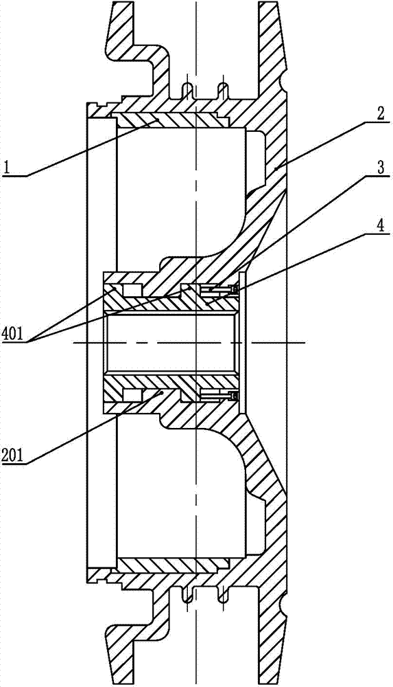
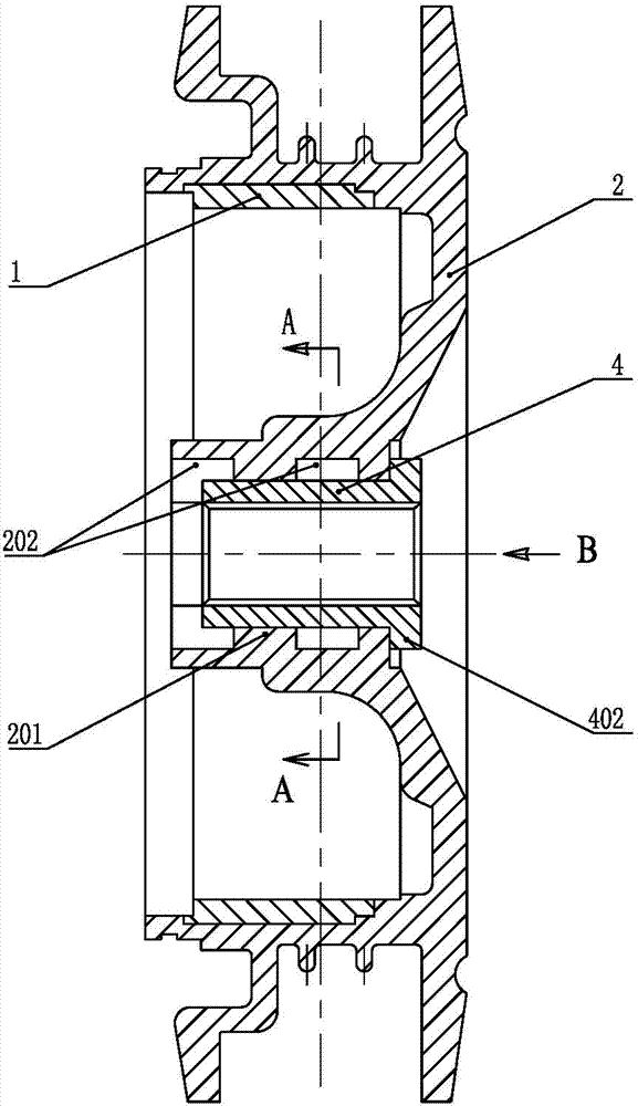
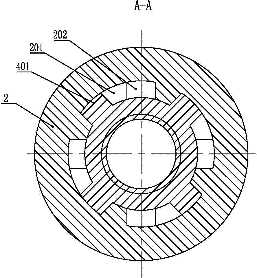
[0028] Such as Figure 1-9 As shown, it is a hub with 4 splines, including a hub body 2, a spline 4 is embedded in the center of the hub body 2, a brake iron ring 1 is arranged on the hub body 2 coaxially with the spline 4, and the inner ring of the spline 4 is provided There are several tooth-shaped keys, and the outer periphery of the spline 4 is provided with a layer of outer layer convex keys 402 and two layers of inner layer convex keys 401, the outer layer convex keys 402 correspond to the outside of the hub body 2, the outer layer convex keys 402 and the inner layer convex keys The keys 401 are respectively evenly distributed in four groups in the circumferential direction. The phase difference between each group of the outer convex keys 402 is 90°, and the phase difference between each group of the inner convex keys 401 is also 90°. The outer convex keys 402 The phase difference between the convex key 401 and the inner layer is 45°. The inner convex keys 401 of differ...


PUM


Abstract

The invention discloses a splined wheel hub and a machining method of the splined wheel hub and belongs to the technical field of wheel manufacturing. The splined wheel hub structurally comprises a wheel hub body, a layer of outer layer convex keys and at least one layer of inner layer convex keys are arranged on the periphery of a spline, an axial groove is formed in the axial direction of a center hole of the wheel hub body, the center hole of the wheel hub body and the axial groove are staggered by an angle for forming key grooves, the inner layer convex keys are installed in the corresponding key grooves one by one in an interference fit mode, and the outer layer convex keys are installed in the axial groove in an interference fit mode at the same time; stop screws are arranged on the end face of the outer side of the wheel hub body and correspond to the outer end faces of the inner layer convex keys. When the splined wheel hub is machined, through rotation and axial extrusion, the inner layer convex keys and the key grooves are made in interference fit, the outer layer convex keys and the axial groove are made in interference fit, and then an inner hole of the spline and a hole in the inner side of a braking iron ring are machined and made coaxial. The splined wheel hub can be used on a wheel and guarantee reliable transmission and braking, and is convenient to assemble and safe to use.

Description

technical field [0001] The invention relates to a wheel hub of a wheel, in particular to a wheel hub adopting spline transmission. Background technique [0002] In the prior art, there is a wheel hub that adopts spline transmission. Its structure mainly includes a hub body, a spline is embedded in the center hole of the hub body, and a brake iron ring is embedded in the wheel hub body. The brake iron The ring is set coaxially with the spline. The processing process is that the processed inner spline is embedded in the wheel hub blank as the center insert of the hub, and then the wheel hub blank is turned, and the brake iron ring is installed after the turning is completed. This processing method cannot guarantee the concentricity of the spline in the center of the hub and the brake iron ring, which will affect the assembly of the next process and the quality of the hub. If the concentricity of the brake ring and the spline cannot be guaranteed, it will have a negative impa...

Claims


Application Information

Patent Timeline
IPC IPC(8): B60B19/00B60B27/00
Inventor 范茂盛方彬唐开秀
Owner JIANGSU YANGGONG POWER MACHINERY
Learn More