Electric hydraulic pump for vehicle power steering

A vehicle power and electro-hydraulic pump technology, applied in the field of hydraulic components, can solve problems such as failure to achieve power adjustment, large energy reactive power loss, and decreased operational stability, and achieve the effects of reducing energy consumption, reducing emissions, and compact structure

Active Publication Date: 2014-10-29
FUXIN DARE AUTOMOTIVE PARTS
View PDF6 Cites 21 Cited by
  • Summary
  • Abstract
  • Description
  • Claims
  • Application Information

AI Technical Summary

Problems solved by technology

[0002] In the traditional automobile power steering system, the mechanical hydraulic steering pump driven by the engine is usually used. In order to ensure the portability of the car in situ steering or low-speed steering, the displacement of the hydraulic pump is determined by the flow rate of the engine at idle speed. The problem with this kind of mechanical hydraulic steering pump is that this system will work regardless of whether the car is turning or not after the car starts, and it does not realize real power adjustment. It uses a constant flow method, which can only solve the problem of steering wheel fluttering. When the vehicle speed is increased, the engine speed increases, the flow rate of the pump increases, and the control valve controls most of the hydraulic oil without entering Instead, the steering gear cylinder flows back into the pump, which causes a large reactive power loss of energy

Method used


Image

  • Electric hydraulic pump for vehicle power steering
  • Electric hydraulic pump for vehicle power steering
  • Electric hydraulic pump for vehicle power steering

Examples


Embodiment Construction

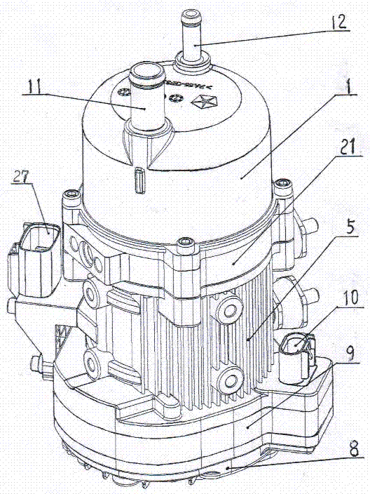
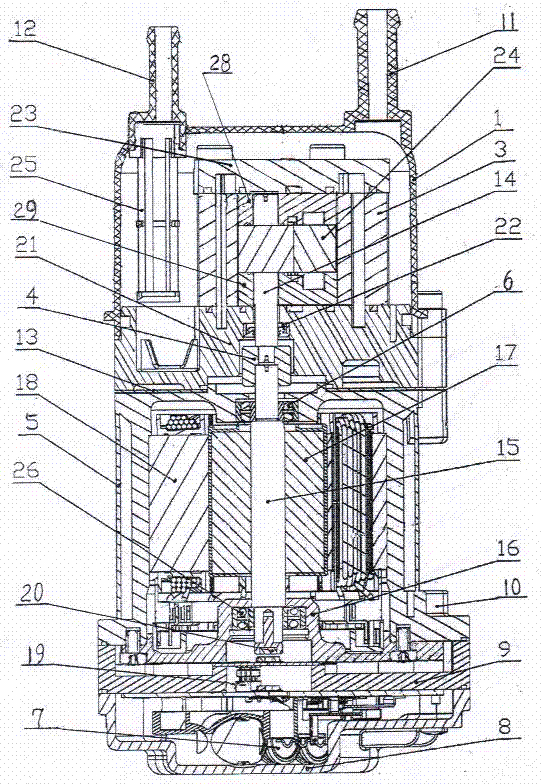
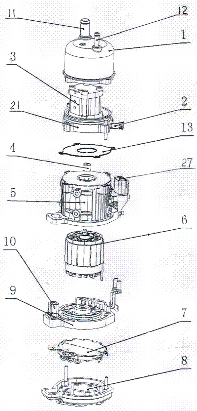
[0011] Examples, see attached Figure 1~3 , the side surface of the front end cover 21 of the vehicle power steering electro-hydraulic pump is threadedly equipped with a pressure relief valve 2, and the middle of the front end cover 21 is fixedly connected with the hydraulic pump body 3 and the front pump cover 23 with bolts. Seat ring one 28, seat ring two 29, driving gear 14, driven gear 24 are respectively housed in the pump body 3 of the hydraulic pump, and the upper and lower shaft ends of the driving gear 14 and the driven gear 24 are movable respectively on the seat ring one 28. On the seat ring 2 29, the driving gear 14 and the driven gear 24 are engaged in transmission connection. The oil pot 1, the front end cover 21, and the housing 5 are fixedly connected by bolts. A gasket 13 is installed between the front end cover 21 and the housing 5. The oil pot 1 is provided with an oil return port 12 and an oil filling port 11 respectively. An oil strainer 25 is fixedly ins...


PUM


Abstract

The invention belongs to hydraulic components and particularly relates to an electric hydraulic pump for vehicle power steering. The upper end and the lower end, where a race I (28), a race II (29), a driving gear (14) and a driven gear (24) are mounted inside respectively, of a hydraulic pump body (3) are movably mounted on the race I (28) and the race II (29) in a penetrating manner respectively; an oil filtration screen (25) is fixedly mounted below the position corresponding to an oil return port (12) in an oil can (1); a cross coupler (4) is connected with the lower end of the driving gear (14) and the upper end of a rotor shaft (15) respectively; the rotor shaft (15) is mounted in a casing (5) in a penetrating manner; a stator (18) is mounted in the casing (5); a rotor (17) is movably mounted in a cavity of the stator (18) in a penetrating manner; a motor front cover (16) and a cooling plate (9) are fixed on the casing (5) through bolts; a shaft head magnet (20) is fixedly mounted at the lower end of the rotor shaft (15); a controller (7) is fixedly mounted on the lower end surface of the cooling plate (9) through a controller front cover (8). The electric hydraulic pump for vehicle power steering is compact in structure, convenient to assemble, high in efficiency and low in noise.

Description

technical field [0001] The invention belongs to hydraulic components, in particular to an electric hydraulic pump for vehicle power steering. Background technique [0002] In the traditional automobile power steering system, the mechanical hydraulic steering pump driven by the engine is usually used. In order to ensure the portability of the car in situ steering or low-speed steering, the displacement of the hydraulic pump is determined by the flow rate of the engine at idle speed. The problem with this kind of mechanical hydraulic steering pump is that this system will work no matter whether it is turning or not after the car is started, and it does not realize real power adjustment. It uses a constant flow method, which can only solve the problem of steering wheel fluttering. When the vehicle speed increases, the engine speed increases, the flow rate of the pump increases, and the control valve controls most of the hydraulic oil. Instead, the steering gear oil cylinder fl...

Claims


Application Information

Patent Timeline
Patent Type & Authority Applications(China)
IPC IPC(8): B62D5/065
Inventor 于大洪余明光杨锦明马奇谢英郑艳双郭志勇王忠伟王时俊
Owner FUXIN DARE AUTOMOTIVE PARTS
Why Eureka
Try Eureka