A brush-fed needle-free electrospinning device and method

An electrospinning and brush technology, which is applied in textiles and papermaking, filament/thread forming, feeding solution to the spinneret, etc., can solve the problems of easy blockage of pinholes, time-consuming and labor-consuming, and regular cleaning, etc. Achieve the effects of modular expansion, simple device structure and uniformity

Active Publication Date: 2016-06-01
JIANGSU NEW HORIZON ADVANCED FUNCTIONAL FIBER INNOVATION CENT CO LTD
View PDF8 Cites 0 Cited by
  • Summary
  • Abstract
  • Description
  • Claims
  • Application Information

AI Technical Summary

Problems solved by technology

However, the traditional pinhole electrospinning device has two bottlenecks on the road to industrialization
One is that the pinholes are easy to block during continuous spinning, and need to be cleaned regularly, which is time-consuming and labor-intensive
Second, the single-pinhole spinning efficiency is extremely low, only 100-1000mg / h
However, this type of feeding method cannot accurately control the thickness and uniformity of the free surface film of the solution.
At the same time, the solution pool of this type of feeding method is generally open, and the solution in the pool volatilizes rapidly during spinning, which will affect the concentration of the spinning solution and the uniformity of the spinning fiber.

Method used


Image

  • A brush-fed needle-free electrospinning device and method
  • A brush-fed needle-free electrospinning device and method
  • A brush-fed needle-free electrospinning device and method

Examples


Embodiment Construction

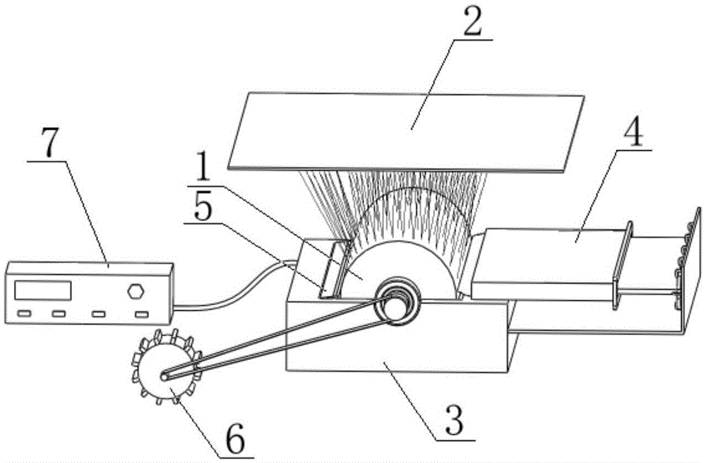
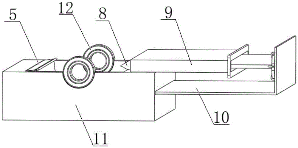
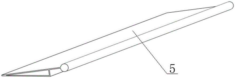
[0022] A brush feeding type needle-free electrostatic spinning device and method of the present invention, such as figure 1 As shown, the device mainly includes a rotary nozzle 1, a receiving plate 2, a concave support 3, a brush feeding system 4, a baffle 5, a motor 6 and an electrostatic generator 7. The concave support 3 is composed of a concave groove 11 and a support bearing 12, and the rotary nozzle 1 is placed on the support bearing 12; the brush feeding system 4 is composed of a brush 8, an injection chamber 9 and a micro-flow metering pump 10. The straight line at the tip of the brush 8 is parallel to the axis of the rotary nozzle 1, and the brush 8 is in contact with the rotary nozzle 1; the baffle plate 5 is placed on the concave groove 11, and the distance between the cylindrical scraper and the rotary nozzle 1 is 0.3-1 mm; the motor 6 The rotating nozzle 1 is controlled by a belt drive to rotate; the receiving plate 2 is placed on the upper end of the rotating noz...


PUM

PropertyMeasurementUnit
diameteraaaaaaaaaa

Abstract

The invention discloses a hairbrush feeding type needle-free electrostatic spinning device and method. The hairbrush feeding type needle-free electrostatic spinning device mainly comprises a rotating spraying head, a receiving plate, a U-type support, a hairbrush feeding system, a baffle, a motor and an electrostatic generator. The U-type support is composed of a U-type groove and supporting bearings, and the rotating spraying head is arranged on the supporting bearings. The hairbrush feeding system is composed of a hairbrush, an injection cavity and a micro-flow measuring pump, the straight line of the pointed end of the hairbrush is parallel to the central axis of the rotating spraying head, and the hairbrush is in contact with the rotating spraying head. The baffle is arranged on the U-type groove, and a cylindrical scraper on the baffle is a certain distance away from the rotating spraying head. The motor controls the rotating spraying head through belt transmission to rotate. The receiving plate is arranged at the upper end of the rotating spraying head. The high-voltage output end of the electrostatic generator is connected with the supporting bearings, and the grounded end of the electrostatic generator and the receiving plate are grounded at the same time. The receiving plate is made of electric conduction metal. The method includes the step that spinning solutions are evenly brushed to the rotating spraying head through the hairbrush to form solution film with the controllable thickness. The phenomenon that a spraying-head type electrostatic spinning device is prone to blocking is overcome by means of the hairbrush structure.

Description

technical field [0001] The invention relates to a brush-feeding type needle-free electrostatic spinning device and method, belonging to the field of electrostatic spinning. Background technique [0002] Nanofiber mat has small diameter, high porosity and large specific surface area, so it can be used in many fields such as air filtration, water treatment, lithium battery separator, etc. However, the traditional pinhole electrospinning device has two bottlenecks on the road to industrialization. One is that the pinholes are easily blocked during continuous spinning, which requires regular cleaning, which is time-consuming and labor-intensive. Second, the single-pinhole spinning efficiency is extremely low, only 100-1000mg / h. However, the flow channel design of the multi-pinhole spinning device is complicated, and the equipment cost is relatively high. Needle-free electrospinning devices have become a research hotspot in the field of electrospinning in recent years. Researc...

Claims


Application Information

Patent Timeline
Patent Type & Authority Patents(China)
IPC IPC(8): D01D13/00D01D5/00D01D1/06
Inventor 杨卫民吴卫逢李好义何雪涛丁玉梅
Owner JIANGSU NEW HORIZON ADVANCED FUNCTIONAL FIBER INNOVATION CENT CO LTD
Why Eureka
Try Eureka