
Electric car air conditioning system with air source heat pump

An air source heat pump and electric vehicle technology, which is applied in the field of refrigeration and air conditioning, can solve the problems that affect the safety of the system operation, the low suction capacity of the compressor, and the high exhaust temperature, so as to improve the heating capacity and heating efficiency and reduce the exhaust gas. Effects of temperature and extended use range

Inactive Publication Date: 2014-10-29
TECHNICAL INST OF PHYSICS & CHEMISTRY - CHINESE ACAD OF SCI
View PDF7 Cites 49 Cited by
  • Summary
  • Abstract
  • Description
  • Claims
  • Application Information

AI Technical Summary

Problems solved by technology

[0003] At present, electric vehicles mainly use PTC (positive temperature coefficient) electric heating for heating in winter, which has low operating efficiency and large power consumption, which will greatly reduce the operating mileage of electric vehicles
Conventional heat pump systems used in automotive air conditioners use two heat exchangers, indoor and outdoor, and switch between heating and cooling modes through a four-way valve, which has poor vibration resistance and reliability
In addition, the conventional air source heat pump system, in the low temperature outdoor environment, the air intake of the compressor is low, the exhaust temperature is high, and the heating capacity and efficiency are greatly reduced, which cannot meet the heating demand and realize low-temperature heating, while the excessively high exhaust The temperature seriously affects the safety of the system operation, making the conventional heat pump system unable to operate normally in the low-temperature environment outside the car in winter

Method used


Image

  • Electric car air conditioning system with air source heat pump
  • Electric car air conditioning system with air source heat pump
  • Electric car air conditioning system with air source heat pump

Examples


Embodiment approach 1

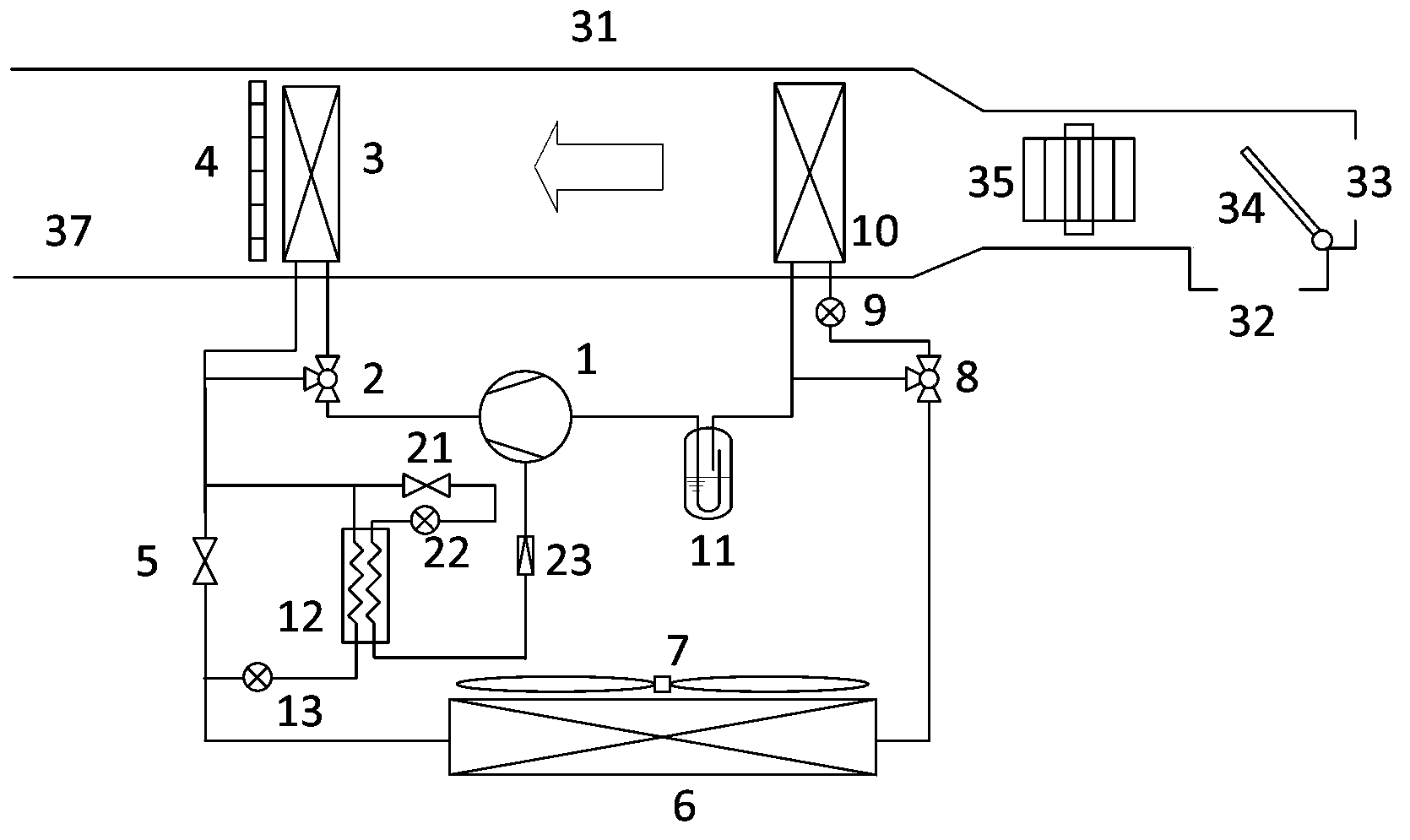
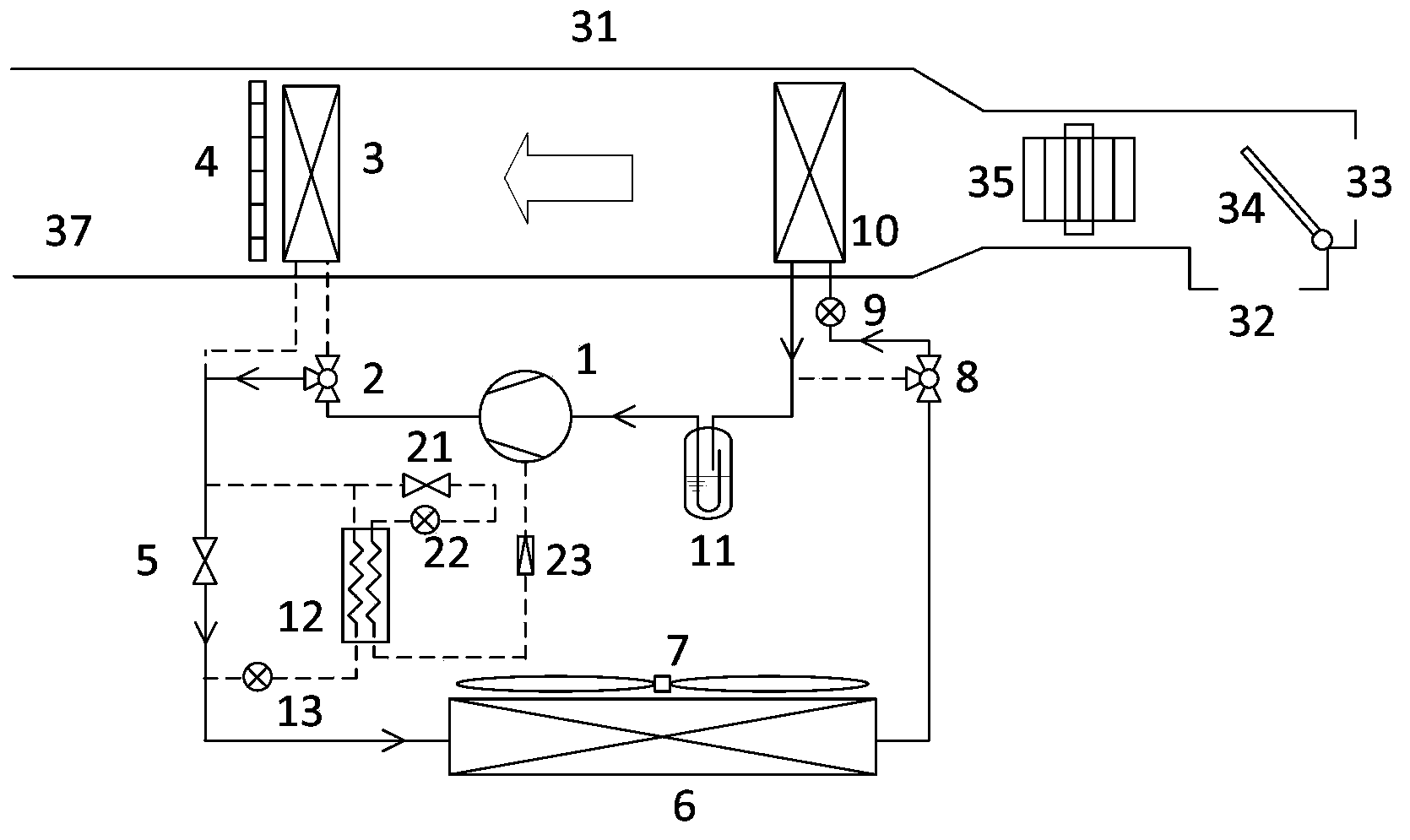
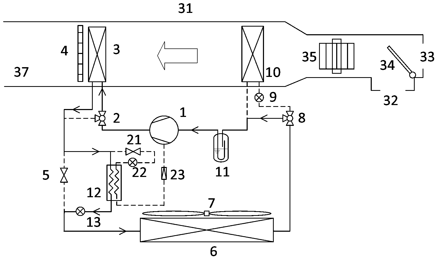
[0032] like figure 1 The electric vehicle air conditioning system shown in the figure adopts low-temperature air-source air-conditioning heat pump technology to realize the conversion of three modes: refrigeration, conventional heating and low-temperature heating; 3, the indoor evaporator 10 set on the return air line of the compressor 1, the outdoor heat exchanger 6 set on the pipeline between the indoor condenser 3 and the indoor evaporator 10, the indoor condenser 3 and the outdoor heat exchanger The parallel first valve 5 between 6, the second three-way valve 8 arranged between the outdoor heat exchanger 6 and the indoor evaporator 10, and the second three-way valve 8 arranged between the inlet of the indoor evaporator 10 The first throttling device 9; the bypass of the second three-way valve 8 is connected to the pipeline before the inlet of the compressor 1 and the indoor evaporator 10.

[0033] A first three-way valve 2 is arranged on the pipeline between the compresso...

Embodiment 2

[0049] Embodiment 2 is to use a three-way valve to control the opening and closing of the refrigerant channel of the indoor condenser in Example 1, and instead use a damper to control the opening and closing of the air channel of the indoor condenser, as Figure 5 shown.

[0050] In the cooling mode, adjust the air valve 36 to state a, close the air duct flowing through the indoor condenser, open the bypass air duct of the indoor condenser, open the first valve 5, adjust the first three-way valve 8 to open the first throttling device 9 and Indoor evaporator 10 access, close its bypass branch, all the other parts are the same as embodiment 1. The indoor (inside the car) return air and the outdoor (outside the car) fresh air are regulated by the air valve 34 and then enter the air duct 31. After being cooled by the indoor evaporator 10 under the action of the fan 35, they are sent into the room through the air duct b, and the indoor is condensed The device 3 is blocked by the a...

Embodiment 3

[0053] like Image 6 As shown, an electric vehicle air conditioning system using air source heat pump, the system uses low temperature air source air conditioning heat pump technology to realize the conversion of three modes of cooling, conventional heating and low temperature heating;

[0054] The electric vehicle air conditioning system includes: a compressor 1, a first three-way valve 2, an indoor condenser 3, a first valve 5, an outdoor heat exchanger 6, a second three-way valve 8, and a first throttling device 9 , an indoor evaporator 10 and a gas-liquid separator 11; the system also includes a flash separator 25, a fourth throttling device 14, a fourth valve 15, a third valve 24, a fifth throttling device 26 and a one-way valve 23; The flash separator and compressor 1 are connected through a return gas pipeline; the difference between it and Embodiment 1 is that the heating and low-temperature heating modes are different:

[0055] In normal heating mode, the first valve...


PUM


Abstract

The invention discloses an electric car air conditioning system with an air source heat pump. The electric car air conditioning system has a refrigerating mode, a conventional heating mode, a low-temperature heating mode and a defrosting mode in an electric car, and a main loop of the air conditioning system comprises a compressor, an indoor condenser arranged on an outlet pipeline of the compressor, an indoor evaporator arranged on an air return pipeline of the compressor, an outdoor heat exchanger arranged on a pipeline between the indoor condenser and the indoor evaporator, a first valve arranged between the indoor condenser and the outdoor heat exchanger, a second three-way valve arranged between the outdoor heat exchanger and the indoor evaporator, and a first throttling device arranged between the second three-way valve and an inlet of the indoor evaporator. A by path of the second three-way valve is connected with an inlet of the compressor. In the low-temperature heating mode of the air conditioning system, a middle air supplementing system operates, and the electric car air conditioning system has the advantages of being reliable in operation, high in heating capacity, high in heating efficiency and the like.

Description

technical field [0001] The invention relates to the field of refrigeration and air conditioning, in particular to an electric vehicle air conditioning system using an air source heat pump. Background technique [0002] Automobile air conditioners maintain the comfort of the car environment by controlling the temperature and humidity inside the car, and improve the safety of the car through defrosting and defogging. It is an important part of the car and the auxiliary equipment that consumes the most energy in the car. Compared with traditional internal combustion engine vehicles or hybrid vehicles, pure electric vehicles do not have an engine as a power source to drive the air conditioning system for cooling operation, and there is no engine waste heat to use for heating and defrosting. [0003] At present, electric vehicles mainly use PTC (positive temperature coefficient) electric heating for heating in winter, which has low operating efficiency and large power consumption...

Claims


Application Information

Patent Timeline
IPC IPC(8): F25B29/00F25B41/04F25B41/06F24F5/00F25B41/20F25B41/31F25B41/34F25B41/37
CPCB60H1/3223
Inventor 田长青秦菲邵双全徐洪波
Owner TECHNICAL INST OF PHYSICS & CHEMISTRY - CHINESE ACAD OF SCI
Learn More