Soil strength test board for wheel

A test bench and wheel technology, applied in wheel testing, force/torque/work measuring instruments, measuring devices, etc., can solve problems such as changing the load force in the vertical direction, and achieve the effect of easy handling and increased diversity

Inactive Publication Date: 2014-10-29
SHANGHAI UNIV
View PDF5 Cites 18 Cited by
  • Summary
  • Abstract
  • Description
  • Claims
  • Application Information

AI Technical Summary

Problems solved by technology

Existing test benches usually change the vertical load off-line (one example is the trolley device suitable for the wheel movement performance test of planetary exploration vehicles disclosed in the Chinese invention patent application number 20061007632

Method used


Image

  • Soil strength test board for wheel
  • Soil strength test board for wheel
  • Soil strength test board for wheel

Examples


Embodiment 1

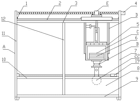
[0022] 1. see Figure 1 to Figure 7 , the wheel soil force test bench, including a test bench support A, a wheel 22 and a soil tank body 8 interacting with the wheel 22, is characterized in that: the soil tank body 8 is placed in the lower part of the test bench support A, The wheels 22 are rolled on the upper surface of the soil tank body 8; the wheels 22 are connected under a variable load mechanism C through a steering mechanism B, and the variable load mechanism C is connected to a vertical and horizontal movement mechanism D The wheel driven drive mechanism E is movably hoisted on the two upper beams 3 of the test bench support A; the rotating shaft of the wheel 22 is directly connected to a wheel active drive mechanism F.

Embodiment 2

[0024] This embodiment is basically the same as Embodiment 1, and the special features are as follows:

[0025] The structure of the test bench support A: two left columns 11 and two right columns 7 are parallel to each other in the vertical direction, and are respectively fixedly installed on four test bench universal wheels 17, and the two upper beams 3 and the two lower beams The crossbeams 9 are parallel to each other along the horizontal direction, and the two ends are fixedly installed on the left column 11 and the right column 7 respectively, and the two middle columns 12 are parallel to the left column 11 and the right column 7, and the two ends are respectively installed on the upper beam 3 and the lower beam 9 Above, the two upper beams 3 are respectively equipped with a linear guide rail seat 2, and a linear guide rail 14 is installed on the linear guide rail seat 2.

[0026] The structure of the wheel active drive mechanism F and the steering mechanism B: the wheel...

Embodiment 3

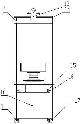
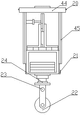
[0030] Such as Figure 1 to Figure 7 As shown, the wheel soil force test bench includes an infrared sensor receiving end 1, a linear guide rail seat 2, an upper beam 3, a screw motor 4, a slide rail 5, a counterweight 6, a right column 7, a soil tank body 8, a lower Beam 9, soil tank beam 10, left column 11, center column 12, screw seat 13, linear guide rail 14, soil tank linear guide rail 15, soil tank linear guide rail seat 16, test bench universal wheel 17, soil tank body universal Wheel 18, soil scraping mechanism 19, infrared sensor transmitter 20, linear displacement sensor 21, wheel 22, vibration sensor 23, reducer 24, six-dimensional force sensor 25, steering motor 26, wheel bracket 27, torque sensor 28, hub motor 29. Angular velocity sensor 30, crank 31, connecting rod 32, magnet slider 33, magnet 34, pressure sensor 35, counterweight box 36, adjustment block 37, chute 38, reducer 39, crank motor 40, screw nut 41, Bolt 42, nut 43, horizontal moving bracket 44, vertic...


PUM


Abstract

The invention relates to a soil strength test board for a wheel. The soil strength test board for the wheel comprises a test board bracket, a wheel and a soil groove body which interacts with the wheel, the soil groove body is arranged at the lower part of the inside of the test board bracket, and the wheel is located at the upper surface of the soil groove body in a rolling press mode; the wheel is connected below a variable load mechanism through a steering mechanism, and the variable load mechanism is connected with a driven wheel drive mechanism through vertical and horizontal moving mechanisms so as to be movably hanged on two upper beams of the test board bracket; the rotating shaft of the wheel is directly connected with an active wheel drive mechanism. The soil strength test board for the wheel can use a counterweight block to change the weight of the soil strength test board for the wheel under an offline state so as to simulate the acting force between the wheel and the ground under different vehicle weights; a slider-crank mechanism changes the distance between two isotropic magnets so as to change the repulsive force there-between to simulate the online real-time vertical load change of the wheel of an air cushion vehicle; the active wheel drive mechanism and the driven wheel drive mechanism simulate the active movement form and driven movement form of the wheel.

Description

technical field [0001] The invention relates to a wheel soil force testing platform, in particular to a wheel soil force testing platform capable of changing the wheel-ground vertical force in real time on-line. Background technique [0002] There are large swamps, tidal flats, deserts and other soft ground environments on the surface of the earth, involving many industrial and agricultural sectors such as petroleum, mining, transportation, fishery, forestry, agriculture, and military fields. When off-road vehicles are running on soft ground, the running mechanism is prone to deep sinking, high resistance, low efficiency, severe skidding, and even inability to drive at all. Therefore, it is necessary to design and develop a soil force test bench for the study of running ) and soft soil, and optimize the design of the walking mechanism based on this to improve the soft ground passability. [0003] The following issues should be considered in the design scheme of the wheel so...

Claims


Application Information

Patent Timeline
IPC IPC(8): G01M17/013G01L5/00
Inventor 顾益楠许烁孙晶任思恺
Owner SHANGHAI UNIV
Why Eureka
Try Eureka