Radar apparatus for vehicle radar system

A radar device and radar system technology, applied in measurement devices, radio wave measurement systems, and re-radiation, etc., can solve problems such as difficulties in wireless signal transceivers, reduction of timeliness, and inability to participate in decision-making on bumper material and thickness. Simplify the assembly process and reduce the effect of wiring

Active Publication Date: 2014-10-29
WISTRON NEWEB
View PDF4 Cites 15 Cited by
  • Summary
  • Abstract
  • Description
  • Claims
  • Application Information

AI Technical Summary

Problems solved by technology

In this case, since the wireless signal transceivers 100 and 102 are separately located on both sides of the rear of the vehicle, the complexity of the relevant signal wiring increases, and the steps of the assembly process also increase, which may affect the reliability or satisfaction of the vehicle.
[0006] On the other hand, since shock-absorbing styrofoam or glass fiber is usually installed in the bumper of the vehicle, the available space is extremely limited. Therefore, the supplier of the blind spot detection system needs to participate in the decision-making of the material and thickness of the bumper during the vehicle design stage. And it is necessary to modify the design of the wireless signal transceiver repeatedly according to the requirements of the vehicle manufacturer, which will also reduce the timeliness
Furthermore, if the sales target of the automotive radar system is the aftermarket, that is, the radar supplier will not be able to participate in the decision on the material and thickness of the bumper. In this case, how to design a wireless signal transceiver suitable for most vehicles appear more difficult

Method used


Image

  • Radar apparatus for vehicle radar system
  • Radar apparatus for vehicle radar system
  • Radar apparatus for vehicle radar system

Examples


Embodiment Construction

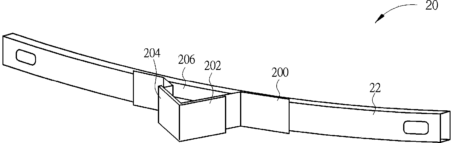
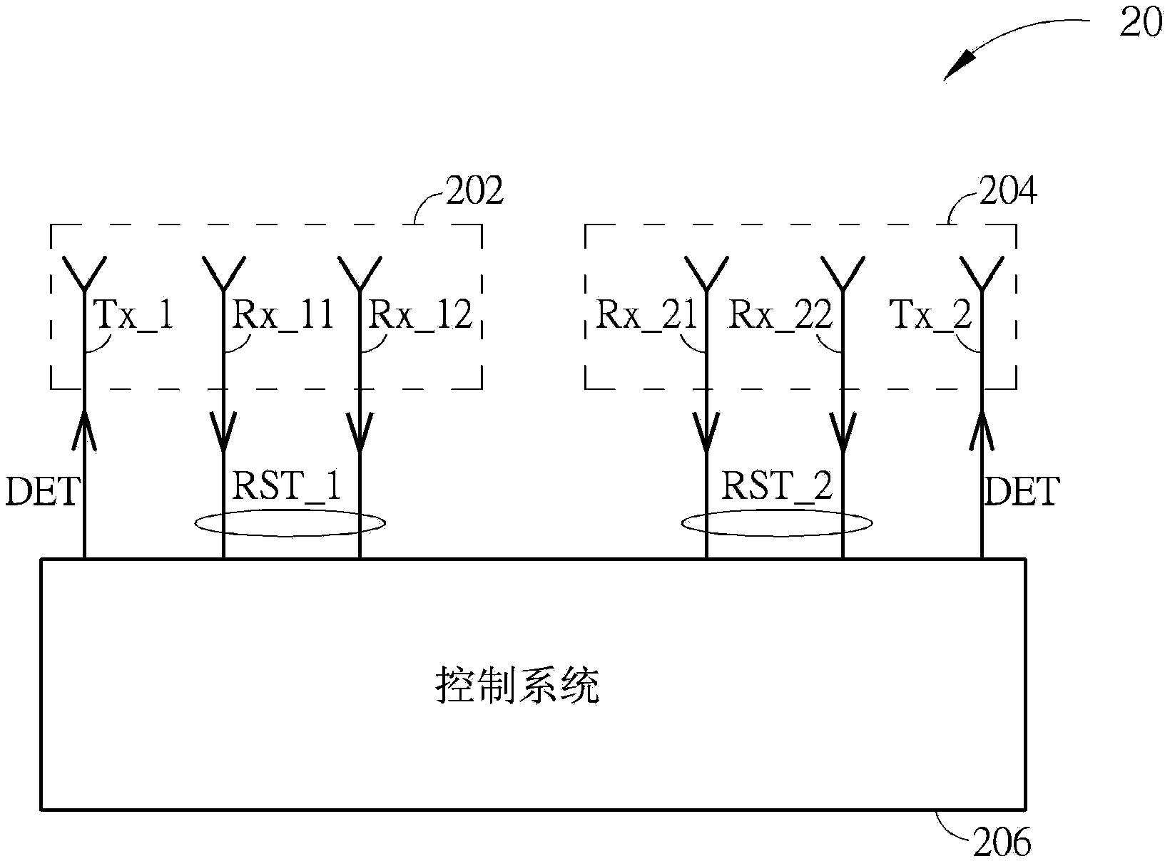
[0063] Please refer to Figure 2A and Figure 2B , Figure 2A is a schematic diagram of the appearance of a radar device 20 according to an embodiment of the present invention, Figure 2B is a functional block diagram of the radar device 20 . The radar device 20 is used in a vehicle radar system, such as a blind spot detection system, and includes a base 200 , a first antenna module 202 , a second antenna module 204 and a control system 206 . The radar device 20 can be installed in a car bumper, for example, on a bumper bar 22 by locking or bonding, but is not limited thereto. Since the radar device 20 integrates the first antenna module 202 , the second antenna module 204 and the control system 206 required for performing blind spot detection, the required wiring can be greatly reduced and the assembly process can be simplified.

[0064] In detail, the first antenna module 202 is fixed on the base 200, which includes a transmitting antenna TX_1 and receiving antennas RX_1...


PUM


Abstract

The invention relates to a radar apparatus for a vehicle radar system. The radar apparatus comprises a base; a first antenna module which includes a first transmitting antenna and a plurality of first receiving antennas, is used for transmitting a detection signal and generating a first signal reception result, and is fixed on the base; a second antenna module which includes a second transmitting antenna and a plurality of second receiving antennas, is used for transmitting a detection signal and generating a second signal reception result, and is fixed on the base; and a control system which is disposed in the base, coupled to the first antenna module and the second antenna module, and used for outputting the detection signals to the first transmitting antenna and the second transmitting antenna and processing the first signal reception result and the second signal reception result. According to the invention, the antenna modules and the control system which are desired for performing blind spot detection can be integrated, the amount of wiring can be therefore significantly reduced and the assembly process is simplified.

Description

technical field [0001] The invention relates to a radar device for a vehicle radar system, in particular to a radar device for a vehicle radar system which can reduce required wiring and simplify the assembly process. Background technique [0002] The blind spot detection system is a vehicle safety protection technology that uses millimeter wave (Millimeter Wave) radar sensing technology to achieve pre-warning. It detects the state of obstacles in the vehicle's blind spot area by means of machine vision image autonomous recognition. If the system detects that a specific obstacle exists in the blind spot, it will actively send out information such as warning lights or warning sounds to the driver, so that the driver can decide the driving direction according to the warning result, and avoid the driver's negligence or blind spots. The occurrence of traffic accidents, its operation concept is briefly shown in figure 1 middle. [0003] Such as figure 1 As shown, the dotted ar...

Claims


Application Information

Patent Timeline
Patent Type & Authority Applications(China)
IPC IPC(8): G01S13/93G01S13/04
CPCG01S13/04G01S13/931G01S2013/9315G01S2013/93272G01S2013/93275
Inventor 萧兴隆陈毅山
Owner WISTRON NEWEB
Why Eureka
Try Eureka