
Storage unit

A technology of memory cell and tunnel insulating layer, applied in the field of storage, can solve the problems of reducing storage cost, affecting storage density, limited channel current, etc., so as to improve reading and storage speed, increase channel width, and increase channel current. Effect

Inactive Publication Date: 2014-10-29
GIGADEVICE SEMICON (BEIJING) INC
View PDF5 Cites 0 Cited by
  • Summary
  • Abstract
  • Description
  • Claims
  • Application Information

AI Technical Summary

Problems solved by technology

[0003] With the continuous shrinking of process nodes, regardless of the electron tunneling oxide layer (ETOX) or SONOS structure, NOR flash memory (Flash) or NAND flash memory (Flash), the channel width of the memory cell has been reduced again and again, so that the planar shape of the tunnel can continue to be used. The insulating layer, the channel width of the storage unit is narrow, and the current after the channel is opened is limited, which affects the reading and storage speed of the stored information, and the shrinkage of the storage node is also limited, which affects the improvement of the storage density. Helps reduce storage costs

Method used


Image

  • Storage unit
  • Storage unit
  • Storage unit

Examples


Embodiment Construction

[0028] The technical solutions of the present invention will be further described below in conjunction with the accompanying drawings and through specific implementation methods. It should be understood that the specific embodiments described here are only used to explain the present invention, but not to limit the present invention. In addition, it should be noted that, for the convenience of description, only parts related to the present invention are shown in the drawings but not all content.

[0029] Figure 4 It is a structural schematic diagram of the X direction of the continuous storage unit of the present invention in the first embodiment; Figure 5 It is a schematic diagram of the X-direction structure of the disconnected memory cell of the present invention according to the first embodiment.

[0030] Such as Figure 4 and Figure 5 As shown, the present invention provides a memory cell, including a control gate 21, a memory cell layer 23, an insulating dielectri...


PUM


Abstract

The invention discloses a storage unit which includes a control gate (21), a storage unit, a control gate layer (23) (21) and a storage unit (23) between the insulating dielectric layer (22), a tunnel insulating layer (24), channel (25), among them, the tunnel insulating layer (24) the channel (25) above is non planar. The present invention insulating layer is non planar design through between the memory cell layer and the channel tunnel, can increase the width of the channel stereo, thereby increasing the channel current of storage unit channel opened, improve the storage information stored and read speed, so as to provide conditions for further reducing process node.

Description

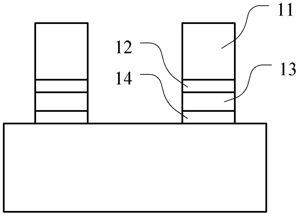
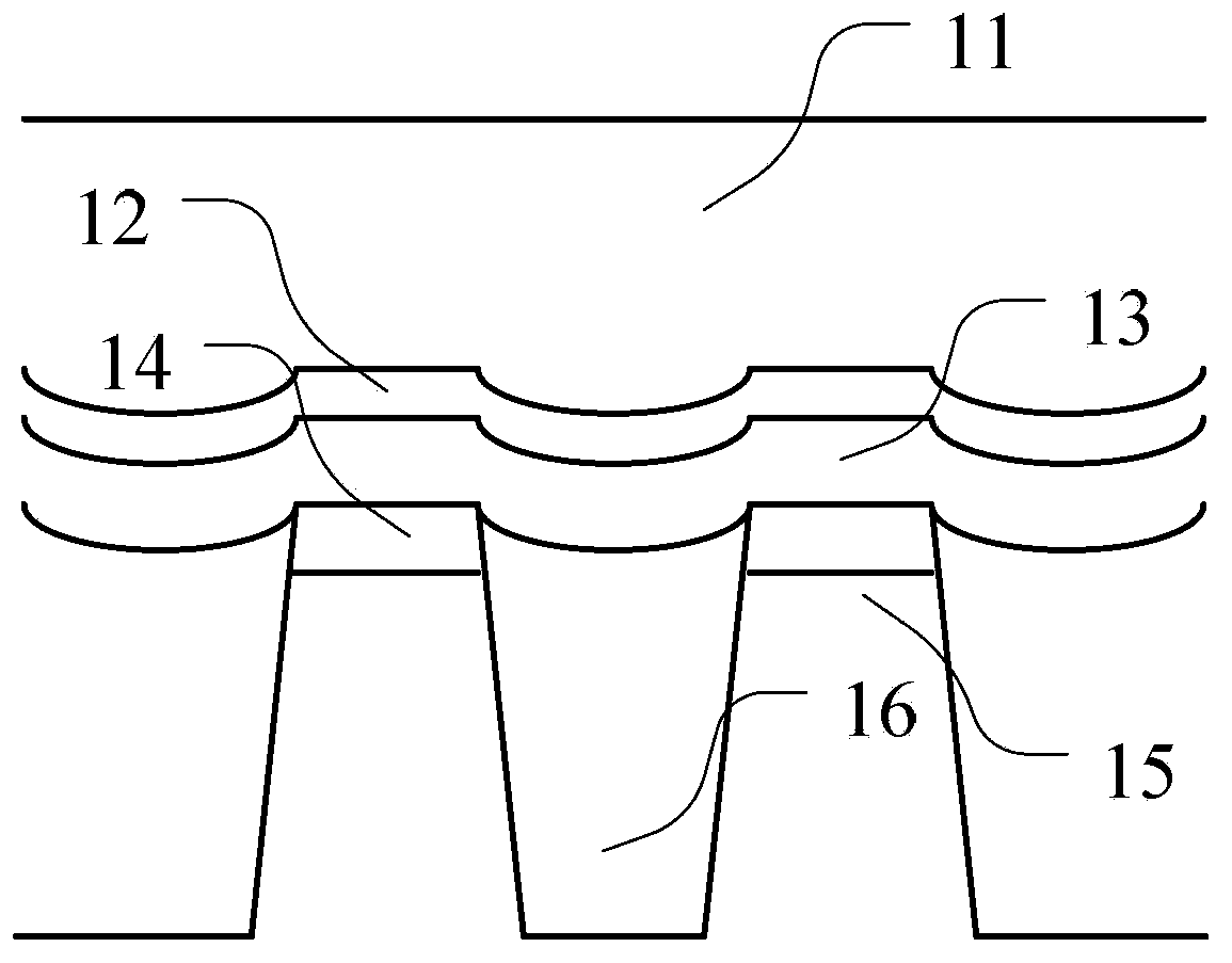
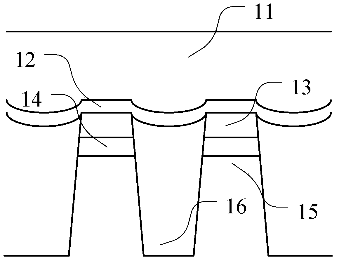
technical field [0001] The invention relates to the field of storage, in particular to a storage unit. Background technique [0002] In the prior art, the tunnel insulating layer between the memory cell layer and the channel is planar, as shown below. figure 1 is a schematic structural diagram of the Y direction of the storage unit in the prior art; figure 2 It is a structural schematic diagram of the X direction of continuous memory cells in the prior art; image 3 It is a schematic diagram of the X-direction structure of the disconnected memory cell in the prior art. From Figure 1 to Figure 3 It can be seen that the memory cell in the prior art includes a control gate 11, a memory cell layer 13, an insulating dielectric layer 12 between the control gate 11 and the memory cell 13, a tunnel insulating layer 14, a channel 15 and two adjacent channels The insulating layer 16 between which the memory cell layer 13, the insulating dielectric layer 12, and the tunnel insula...

Claims


Application Information

Patent Timeline
IPC IPC(8): H01L27/115H01L29/10H10B69/00
Inventor 吴楠冯骏
Owner GIGADEVICE SEMICON (BEIJING) INC
Learn More