
Cooling device of high-power solid laser

A technology of solid-state lasers and cooling devices, applied in the field of lasers, can solve problems such as water leakage, large volume, and complicated pipelines, and achieve the effects of improving temperature uniformity, accelerating heat transfer, and reducing resistance

Active Publication Date: 2014-10-29
11TH RES INST OF CHINA ELECTRONICS TECH GROUP CORP
View PDF5 Cites 6 Cited by
  • Summary
  • Abstract
  • Description
  • Claims
  • Application Information

AI Technical Summary

Problems solved by technology

[0005] The technical problem to be solved by the present invention is to provide a high-power solid-state laser heat dissipation device to overcome the problems of water leakage, large volume and complicated pipelines that may be caused by heat dissipation methods in the prior art

Method used


Image

  • Cooling device of high-power solid laser
  • Cooling device of high-power solid laser
  • Cooling device of high-power solid laser

Examples


no. 1 example

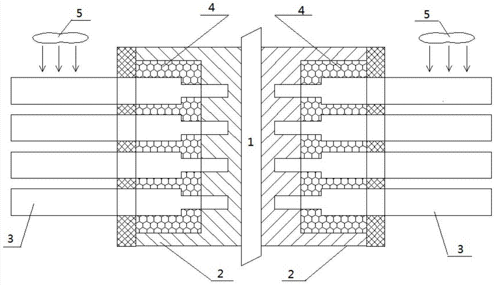
[0028] In the first embodiment of the present invention, a cooling device for a solid-state laser, such as figure 1 As shown, it includes the following components: a heat sink 2, a split heat pipe 3, a phase change microcapsule plate 4 and a cooling fan 5, wherein the heat sink 2 can be a copper heat sink. One side of the heat sink 2 is in close contact with the gain medium 1 of the high-power solid-state laser through low-contact thermal-resistance welding, and the low-contact thermal-resistance welding may be indium evaporation or the like.

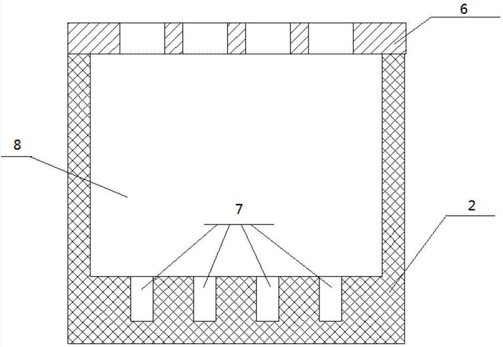
[0029] Such as figure 2 As shown, the other side of the heat sink 2 is provided with an end cover 6 , a groove 7 conforming to the shape of the evaporation section of the split heat pipe 3 , and a cavity 8 for matching the phase change microcapsule plate. The end cap 6 is used to fix the split heat pipe 3 and prevent the liquid from overflowing from the heat sink due to the rupture of the phase change microcapsules.

[0030] The phas...

no. 2 example

[0040] The second embodiment of the present invention is a heat dissipation device for a high-power solid-state laser. The heat dissipation device of this embodiment is substantially the same as that of the first embodiment, the only difference being that the heat dissipation device of this embodiment includes the following components: Heat sink, shunt heat pipe and cooling fan without phase change microcapsule plate.

[0041] Among them, one side of the heat sink is in close contact with the gain medium of the high-power solid-state laser, and the other side of the heat sink is provided with a groove that matches the shape of the evaporation section of the split heat pipe;

[0042] When the split heat pipe is inserted into the groove of the heat sink, the condensation section of the split heat pipe is located in the air, and the heat dissipation of the condensation section is accelerated by the cooling fan.


PUM


Abstract

The invention discloses a cooling device of a high-power solid laser. The cooling device of the high-power solid laser comprises a heat sink, a shunting type heat pipe and a cooling fan, wherein one side of the heat sink is in firm contact with gain medium of the high-power solid laser, and the other side of the heat sink is provided with a groove matched with the evaporation section of the shunting type heat pipe in shape; when the shunting type heat pipe is inserted in the groove of the heat sink, the condensing section of the shunting type heat pipe is located in the air, and the cooling fan accelerates the cooling of the condensing section. The cooling device of the high-power solid laser is capable of effectively lowering the gain medium temperature, reducing the thermal stress deformation of the gain medium due to uneven temperature and improving the laser beam quality and output power. The cooling device of the high-power solid laser overcomes the problems of water leakage, large volume, complex pipeline and the like which may be caused by the cooling mode of the prior art.

Description

technical field [0001] The invention relates to the technical field of lasers, in particular to a heat dissipation device for high-power solid-state lasers. Background technique [0002] High-power solid-state lasers have the advantages of high efficiency, good beam quality, small size, and compact structure, and have important applications in industry, scientific research, and national security. [0003] Only a small part of the total input energy of a solid-state laser is converted into laser output, and most of the rest is converted into waste heat of the gain medium. During the working process of the solid-state laser, due to the uneven distribution of the pump light field and the uneven external cooling, an uneven temperature field is formed inside the gain medium, thereby generating thermal stress, and causing a certain change in the optical properties of the crystal, which in turn causes stress Birefringence, thermal lens effect, depolarization effect, and even fract...

Claims


Application Information

Patent Timeline
Patent Type & Authority Applications(China)
IPC IPC(8): H01S3/042
Inventor 吕坤鹏刘刚唐晓军刘磊赵鸿张大勇刘洋王文涛
Owner 11TH RES INST OF CHINA ELECTRONICS TECH GROUP CORP
Learn More