Bar wound stator winding layout with long-pitched and short-pitched coils

A long-pitch, short-pitch technology, applied in the field of stator components, can solve the problem of lack of conductor space

Active Publication Date: 2014-10-29
GM GLOBAL TECH OPERATIONS LLC
View PDF3 Cites 26 Cited by
  • Summary
  • Abstract
  • Description
  • Claims
  • Application Information

AI Technical Summary

Problems solved by technology

However, the lack of a conductor-to-conductor slot liner can expose the conductors to non-optimal voltage potentials within the stator slots (between conductors)

Method used


Image

  • Bar wound stator winding layout with long-pitched and short-pitched coils
  • Bar wound stator winding layout with long-pitched and short-pitched coils
  • Bar wound stator winding layout with long-pitched and short-pitched coils

Examples


Embodiment Construction

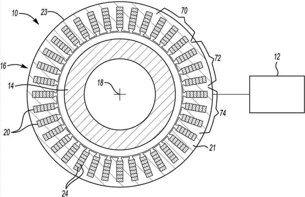
[0016] Referring to the drawings, in which like reference numerals refer to like or similar components throughout the several views, figure 1 is a schematic partial cross-sectional view of an electric motor / generator or electric traction machine, referred to herein as electric machine 10 . The electric machine 10 may be used in a vehicle 12 . Vehicle 12 may be any passenger or commercial vehicle, such as a hybrid electric vehicle, including a plug-in hybrid electric vehicle, an extended-range electric vehicle, or other vehicles. Electric machine 10 may include any device configured to generate electric machine torque, for example, by converting electrical energy into rotational motion. For example, electric machine 10 may be configured to receive electrical power from a power source, such as a battery array (not shown). The power supply can be configured to store and output electrical energy. The vehicle 12 may include an inverter (not shown) for converting the DC voltage f...


PUM


Abstract

A stator assembly includes a plurality of stator slots defining a plurality of slot layers. The assembly includes a plurality of hairpins each having respective first and second legs positioned in respective ones of the slot layers. Each of the hairpins is one of a short-pitched coil, a long-pitched coil and a full-pitched coil. The short-pitched, long-pitched and full-pitched coils are configured to extend over a first, second and third number of the stator slots, respectively. The hairpins may be divided into first, second, third, fourth, fifth and sixth hairpin layers. One of the hairpin layers includes at least one short-pitched coil, and another of the hairpin layers includes at least one long-pitched coil. The first, third and fifth hairpin layers each may include at least two short-pitched coils while the second, fourth and sixth hairpin layers each may include at least two long-pitched coils.

Description

technical field [0001] The present disclosure relates generally to stator assemblies in electrical machines, and more particularly to winding arrangements for bar wound stator assemblies. Background technique [0002] The electric machine includes a rotor assembly that is rotatable relative to the stator assembly. The stator assembly generally includes a plurality of stator windings inserted into slots of the stator assembly. Bar wound stator assemblies are sometimes used in electric motors to improve motor thermal and overall performance. A typical stripwound construction uses a slot liner surrounding the slot and between the conductors. Eliminating slot liners disposed between conductors within the stator slots will improve copper slot filling and thus improve the efficiency of the electric machine. However, the lack of a conductor-to-conductor slot liner can expose the conductors to non-preferred voltage potentials (between conductors) within the stator slots. Conten...

Claims


Application Information

Patent Timeline
Patent Type & Authority Applications(China)
IPC IPC(8): H02K3/12H02K3/28
CPCH02K3/28H02K3/04H02K3/12
Inventor K.M.拉曼S.朱科维克P.J.萨瓦吉安
Owner GM GLOBAL TECH OPERATIONS LLC
Why Eureka
Try Eureka