
Three-axle single-tire loaded electric bus

An electric bus, single-tire technology, applied in the field of buses, can solve the problems of inconvenience for passengers to get up and seat, large load on a single axle, etc., and achieve the effects of convenient seating, optimal power output, and lower seat height.

Inactive Publication Date: 2014-11-05
中植新能源汽车有限公司
View PDF11 Cites 7 Cited by
  • Summary
  • Abstract
  • Description
  • Claims
  • Application Information

AI Technical Summary

Problems solved by technology

Existing electric new energy buses generally use double bridges, the front axle is used as the steering axle, and the rear axle is used as the driving axle. When the rear axle of the new energy bus adopts the centralized drive mode, the structure of the drive system is limited. When the inner floor of the car is low-floor, the position of the inner floor of the car corresponding to the drive axle and tires is higher, and the seats installed in these positions are higher. , it is not convenient for the occupant to get up and sit down

Method used


Image

  • Three-axle single-tire loaded electric bus
  • Three-axle single-tire loaded electric bus
  • Three-axle single-tire loaded electric bus

Examples


Embodiment 1

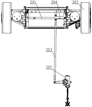
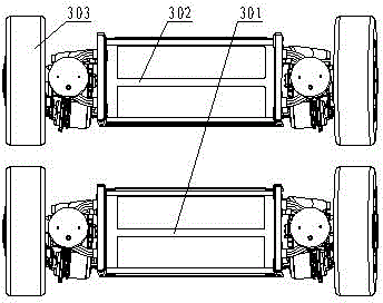
[0023] Such as figure 1 As shown, an electric bus carried by a three-axle single tire includes a chassis 1, a steering mechanism 2 and a driving mechanism 3, wherein the steering mechanism 2 and the driving mechanism 3 are fixed on the chassis 1, and the steering mechanism 2 is located on the driving mechanism 3 On the front side, the steering mechanism 2 of this embodiment includes a steering axle 201 and two steering wheels 202 respectively arranged on both sides of the steering axle 201 . The drive mechanism 3 of the present embodiment includes a drive axle, an electric drive system and a drive wheel 303, wherein the drive axle includes a first drive axle 301 and a second drive axle 302, and the first drive axle 301 and the second drive axle 302 are all arranged laterally And parallel to each other, the first driving axle 301 and the second driving axle 302 have the same horizontal height and have a certain distance in the longitudinal direction. The electric drive system ...

Embodiment 2

[0026] Such as figure 2 As shown, this embodiment makes the following further limitations on the basis of Embodiment 1: the steering mechanism 2 of this embodiment also includes a trailing rod 203 and a steering booster 205, wherein a steering rocker 204 is connected to the steering axle 201 , the two ends of the trailing rod 203 are respectively connected to the steering booster 205 and the steering rocker arm 204 .

[0027] When this embodiment is applied, the steering booster 205 drives the longitudinal tie rod 203 to move, and the longitudinal tie rod 203 transmits power to the steering rocker arm 204 on the steering axle 201, and under the driving action of the steering rocker arm 204, the steering of the steering axle 201 is realized. .

Embodiment 3

[0029] This embodiment makes the following further limitations on the basis of Embodiment 2: the steering rocker arm 204 of this embodiment includes a horizontally arranged transverse connecting plate and a longitudinally arranged longitudinal connecting plate, wherein the front end of the longitudinal connecting plate and the transverse connecting plate Connection, the longitudinal connecting plate is connected with the transverse connecting plate to form an "L" shape as a whole. In order to increase the structural strength of the steering rocker arm 204, the transverse connection plate and the longitudinal connection plate of the steering rocker arm 204 are integrated into one body in this embodiment. In the present embodiment, the steering rocker arm 204 on the steering bridge 201 is arranged on the steering bridge 201 through the limit pin passing through the connecting portion of the transverse connecting plate and the longitudinal connecting plate, and the steering rockin...


PUM


Abstract

The invention discloses a three-axle single-tire loaded electric bus. The bus comprises a chassis, a steering mechanism and a driving mechanism, wherein the steering mechanism and the driving mechanism are fixed on the chassis, the steering mechanism is positioned on the front side of the driving mechanism, and the steering mechanism comprises a steering axle and two steering wheels respectively arranged on both sides of the steering axle; the driving mechanism comprises driving axles, electric drive systems and driving wheels, the driving axles comprise a first driving axle and a second driving axle which are both horizontally arranged and in parallel each other, the driving wheels and the electric drive systems enabling the driving wheels to rotate are respectively arranged on the left sides and the right sides of the first driving axle and the second driving axle, and the electric drive systems are fixed on the driving axles. When the bus disclosed by the invention is applied, the steering wheels, the driving wheels and the electric drive systems, of which the volumes are small, can be adopted, so that altitude differences between bosses, corresponding to the mounting positions of the steering wheels, the driving wheels and the electric drive systems, on a bottom plate of a carriage, and the floor of the carriage can be reduced. After seats are arranged on the bosses, crews can take seats and stand up conveniently.

Description

technical field [0001] The invention relates to a bus, in particular to an electric bus with three bridges and a single tire. Background technique [0002] In recent years, people have paid more and more attention to energy conservation and environmental protection. Electric new energy buses such as pure battery electric buses, hybrid buses, extended-range buses, dual-source trackless electric buses, and trackless electric buses have energy-saving features. The advantages of emission reduction and the rapid development. Existing electric new energy buses generally use double bridges, the front axle is used as the steering axle, and the rear axle is used as the driving axle. When the rear axle of the new energy bus adopts the centralized drive mode, the structure of the drive system is limited. When the inner floor of the car is low-floor, the position of the inner floor of the car corresponding to the drive axle and tires is higher, and the seats installed in these position...

Claims


Application Information

Patent Timeline
IPC IPC(8): B60K1/00B60K7/00B62D7/00
Inventor 徐加凌
Owner 中植新能源汽车有限公司
Learn More