A columnar hydraulic tappet and its plunger preparation method
A hydraulic tappet and plunger technology, applied in mechanical equipment, engine components, machines/engines, etc., can solve problems such as valve clearance cannot be eliminated, complex processing technology, increased noise, etc., to reduce the risk of air mixing into high-pressure chambers , The molding process is simple and the friction resistance is large
- Summary
- Abstract
- Description
- Claims
- Application Information
AI Technical Summary
Problems solved by technology
Method used
Image
Examples
Embodiment 1
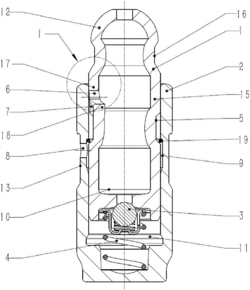
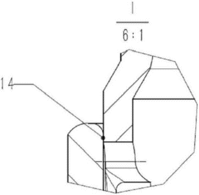
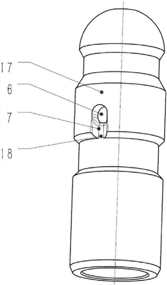
[0056] Such as Figure 1A , Figure 1B As shown, the columnar hydraulic tappet used in the engine valve train has a pot-shaped housing (2), and an axially slidable plunger is arranged in the inner cavity of the housing (2) (1). There is a high-pressure chamber (11) between the lower end surface of the plunger (1) and the housing (2), and the high-pressure chamber (11) can be closed by a one-way valve (3) located at the lower end of the plunger (1). There is a return spring (4) connecting the plunger (1) and the housing (2) in the high-pressure chamber (11). On the outer diameter of the housing (2) there is an outer ring groove (13) for the circulation of the hydraulic medium, and on the radial inner side of the housing (2) there is an inner ring groove (9) for the circulation of the hydraulic medium. One or more oil holes (8) for hydraulic medium circulation are arranged between the inner ring groove (9) of the casing and the outer ring groove (13) of the casing. The outer ...
Embodiment 2
[0061] Such as Figure 4A , Figure 4B As shown, the difference from Embodiment 1 is that the side walls at both ends of the oil groove (7b) are not parallel, and are in the shape of an outward expansion, as shown in the figure, which increases the flow area and facilitates the smooth flow of oil into the plunger Oil inlet hole (6b).
Embodiment 3
[0063] As shown in Figure 5A, Figure 5B, Figure 5C As shown, the difference from Embodiment 1 is that the shape of the plunger oil inlet hole (6c) is a circular hole, the shape of the oil groove (7c) is a concentric semicircle with a diameter larger than the plunger oil inlet hole (6c) at the top, and a concentric semicircle at the bottom. The sidewalls at both ends are tangent to the concentric semicircle, and the sidewalls at both ends are parallel or outwardly expanded; the circular sidewall of the oil groove (7c) does not coincide with the hole wall of the oil inlet hole (6c), and the oil inlet hole (6c) There is a concave tapered surface (20c) on the outside, which prevents the air from being brought in when the oil enters the plunger oil inlet hole (6c).
PUM
 Abstract
Description
Claims
Application Information
 - R&D
- Intellectual Property
- Life Sciences
- Materials
- Tech Scout
- Unparalleled Data Quality
- Higher Quality Content
- 60% Fewer Hallucinations
Browse by: Latest US Patents, China's latest patents, Technical Efficacy Thesaurus, Application Domain, Technology Topic, Popular Technical Reports.
© 2025 PatSnap. All rights reserved.Legal|Privacy policy|Modern Slavery Act Transparency Statement|Sitemap|About US| Contact US: help@patsnap.com


