Forced seal valve with modular design and angular travel operation

A modular design, forced sealing technology, applied in valve devices, mechanical equipment, cocks including cut-off devices, etc. Valve seat sealing surface scouring and other problems, to reduce wear, save maintenance time, and improve the effect of sealing specific pressure

Inactive Publication Date: 2014-11-05
JIANGSU RELIABLE MECHANICAL EQUIP CO LTD
View PDF8 Cites 10 Cited by
  • Summary
  • Abstract
  • Description
  • Claims
  • Application Information

AI Technical Summary

Problems solved by technology

However, ordinary ball valves have the following two disadvantages: First, during the switching process, a large part of the medium will flow through the valve cavity and then flow downstream. The sealing surface of the valve seat forms severe erosion, and both the ball and the valve seat are prone to wear; second, no matter where the ball is relative to the valve seat, the pressure between the two is the same, that is, in any valve position, the pressure between the two is the same. The sealing specific pressure between them is the same, which makes the choice of sealing specific pressure between the two a dilemma: choosing a higher sealing specific pressure will accelerate the wear of the ball sealing surface and the seat sealing surface, and choosing a lower sealing specific pressure will accelerate the wear of the sealing surface of the ball and the seat. The sealing specific pressure will not guarantee the sealing performance of the valve
However, the wedge gate valve is a multi-turn operation, the switching process takes a long time, and the operation is not convenient enough

Method used


Image

  • Forced seal valve with modular design and angular travel operation
  • Forced seal valve with modular design and angular travel operation
  • Forced seal valve with modular design and angular travel operation

Examples


Embodiment Construction

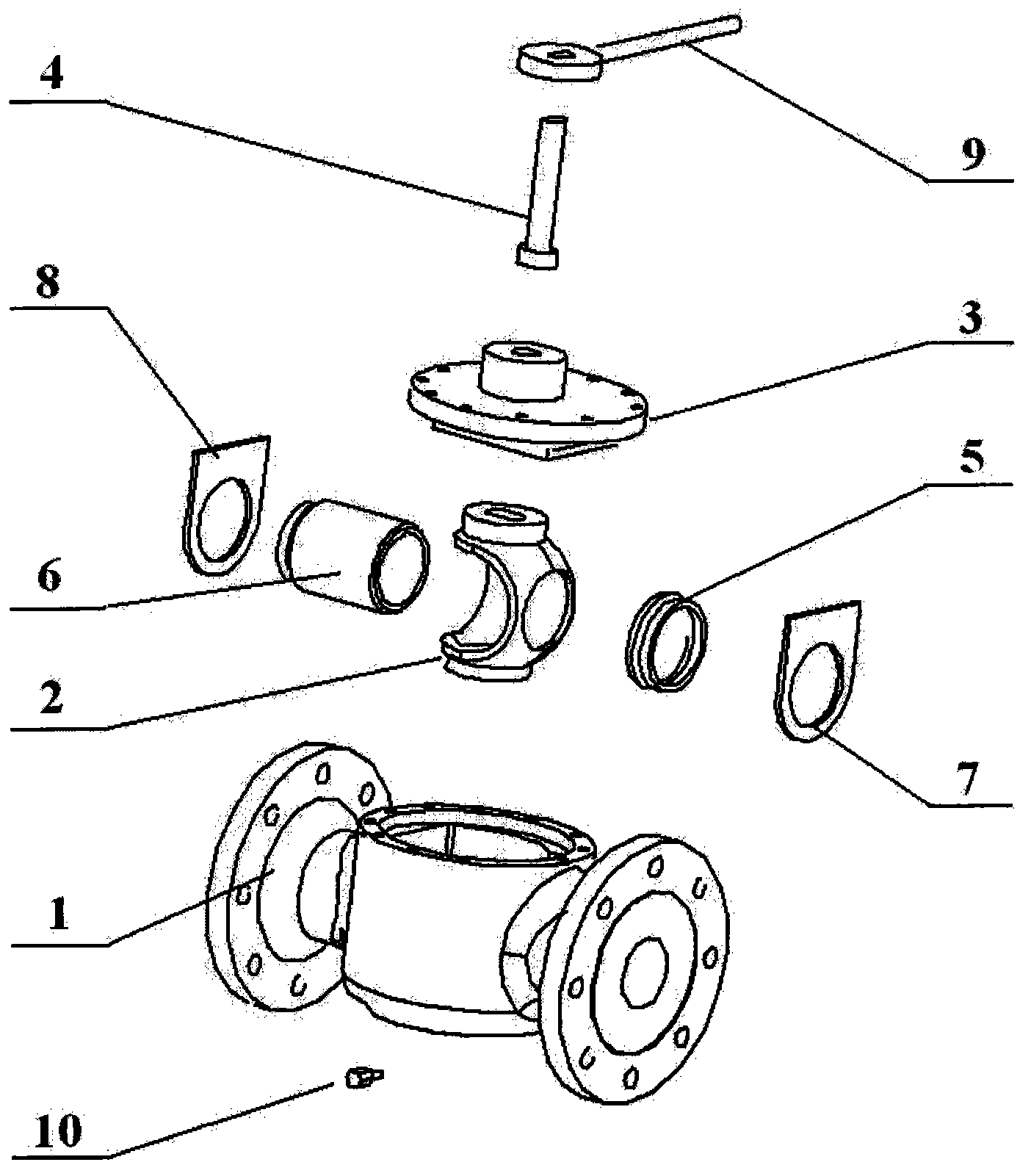
[0020] A forced seal valve with modular design and angular stroke operation, its main components include: valve body 1, opening and closing member 2, valve cover 3, valve stem 4, valve seat 5, guide tube 6, valve seat support plate 7, Guide tube support plate 8, operating mechanism 9, blowdown valve 10. Such as figure 1 shown.

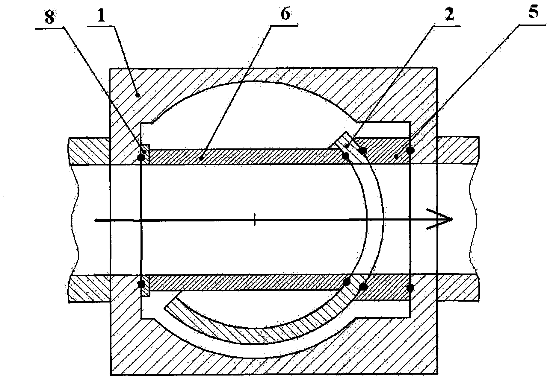
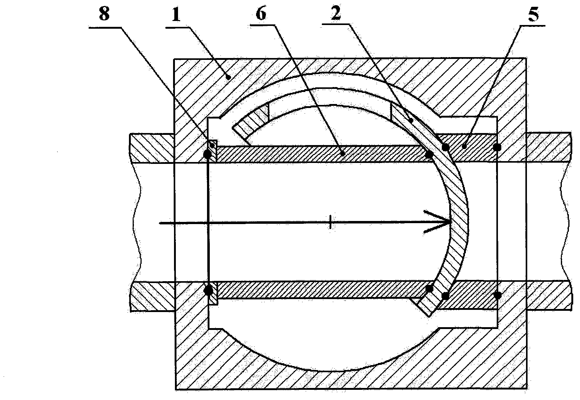
[0021] The opening and closing part 2 is connected with the valve stem 4, and the opening and closing part 2 is driven to rotate by rotating the valve stem 4 to change the relative relationship between the flow channel of the opening and closing part 2 and the diameter of the valve seat 5 to open and close the flow of the medium. Purpose. When the flow channel area of ​​the opening and closing part 2 is connected with the diameter area of ​​the valve seat 5 by 100%, the valve is in the fully open position; when the flow channel area of ​​the opening and closing part 2 is isolated from the diameter area of ​​the valve seat 5 by 100%, The valve is in ...


PUM


Abstract

The invention relates to a forced seal valve with a modular design and angular travel operation; and the main parts of the forced seal valve comprise a valve body, an opening / closing piece, a valve cover, a valve rod, a valve base, a guide cylinder, a valve base support plate, a guide cylinder support plate, an operation mechanism and a blow-down valve. The opening / closing piece is arranged between the valve base and the guide cylinder, and the convex surface and concave surface thereof are mutually eccentric spherical surface structures; and the thickness of each place of the opening / closing piece can be adjusted through adjusting the opposite positions of the spherical centers of the convex spherical surface and the concave spherical surface, so that the seal specific pressure between the opening / closing piece and the valve base can be adjusted when the valve is positioned in different valve positions, and the valve can be forcedly sealed in several valve positions. In addition, the opening / closing piece, the valve rod, the valve base, the guide cylinder, the valve base support plate, the guide cylinder support plate and the valve cover can be produced to one module; and after a fastening piece for connecting the valve cover with the valve body is dismantled, the whole module can be pulled out from the valve, so that the wearing parts of the valve are modularly replaced.

Description

technical field [0001] The invention relates to a valve, in particular to a forced seal valve with a modular design and angular stroke operation which is convenient for replacing a valve core. Background technique [0002] As the "throat" of various pipeline systems in petroleum, chemical, electric power, metallurgy, papermaking and other industries, valves are widely used in the above industries, and ball valves and wedge gate valves are the most widely used valve types. [0003] Ordinary ball valves generally include valve body, valve stem, valve cover, ball, valve seat, etc. The valve stem is connected to the ball through transmission, so that the ball rotates to change the relative relationship between the ball flow channel and the valve seat to achieve opening and closing. medium purpose. The operation of the ball valve is usually a 90° angular stroke operation, which has the advantages of quick switching and convenient operation, and the sealing surface of the valve s...

Claims


Application Information

Patent Timeline
Patent Type & Authority Applications(China)
IPC IPC(8): F16K5/06F16K5/12
CPCF16K5/0605F16K5/0636F16K5/12
Inventor 刘海亮张在晓王磊赵寿军
Owner JIANGSU RELIABLE MECHANICAL EQUIP CO LTD
Why Eureka
Try Eureka