Water level flow sensor, water level flow monitoring system and water level flow monitoring method

A flow sensor and flow monitoring technology, which is applied in the direction of measuring flow/mass flow, liquid/fluid solid measurement, liquid level indicator for physical variable measurement, etc., can solve the inconvenience of automatic transmission of digital and graphic information, water level flow calibration work Large quantity, no guarantee of measurement accuracy, etc., to achieve the effect of easy real-time observation, saving manpower, and easy promotion and use

Inactive Publication Date: 2014-11-05
NORTH CHINA UNIV OF WATER RESOURCES & ELECTRIC POWER
View PDF9 Cites 11 Cited by
  • Summary
  • Abstract
  • Description
  • Claims
  • Application Information

AI Technical Summary

Problems solved by technology

Although it is simple and easy to use hydraulic structures to measure water, the error is relatively large. In addition, due to the aging, deformation, and erosion of hydraulic structures, the measurement accuracy is not guaranteed.
Using special water measuring equipment and facilities to measure water, the construction cost of the facilities is high, and the water flow in the channel has a great impact on the observation accuracy, such as sedimentation, floating objects, etc.; and the calibration of the water level and flow is a large workload, which is not easy to implement Automatic transfer of numerical and graphic information

Method used


Image

  • Water level flow sensor, water level flow monitoring system and water level flow monitoring method
  • Water level flow sensor, water level flow monitoring system and water level flow monitoring method
  • Water level flow sensor, water level flow monitoring system and water level flow monitoring method

Examples


Embodiment 1

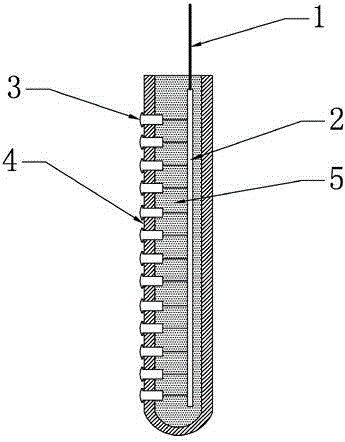
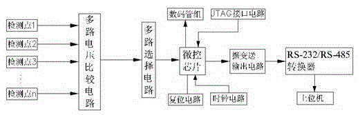
[0033] Embodiment 1: a kind of water level flow sensor, see Figure 1 to Figure 4 , including a water level detection rod, the water level detection rod includes a housing 4, on the outer surface of the housing 4 along its axis direction, a plurality of contacts for connecting with an external circuit (circuit board 2) are provided at an equidistant distance of 2.0 mm 3. The contact 3 is a stainless steel screw, and the screw cap on the stainless steel screw is set on the outer surface of the housing 4, such as figure 1shown in . The water level flow sensor also includes a multi-way voltage comparison circuit correspondingly connected to the above-mentioned contact 3, a multi-way selection circuit correspondingly connected to the multi-way voltage comparison circuit and used to receive the output voltage of the multi-way voltage comparison circuit, and a multi-way selection circuit for receiving the output voltage of the multi-way voltage comparison circuit. The main control ...


PUM


Abstract

The invention provides a water level flow sensor, a water level flow monitoring system and a water level flow monitoring method. The water level flow sensor comprises a water level measuring rod with multiple contacts, a multipath voltage comparison circuit connected with the contacts, a multipath selection circuit correspondingly connected with the multipath voltage comparison circuit, a master control circuit for receiving signals output by the multipath selection circuit, and a data transmitting and output circuit connected with the master control circuit. The water level flow monitoring system comprises an upper computer and the water level flow sensor which are correspondingly connected through an RS-232/RS-485 converter. The water level flow sensor and the water level flow monitoring system have the advantages that water level flow in channels can be measured in water continuously, accurately and quickly, results can be displayed in a digital tube and the upper computer, the water level flow sensor and the water level flow monitoring system are corrosion resistant, long in service life and stable in operation, and the like.

Description

technical field [0001] The invention relates to the field of water level and flow monitoring, in particular to a water level and flow sensor for detecting flow, a water level and flow monitoring system and a water level and flow monitoring method. Background technique [0002] At present, my country is a country with a large water shortage, and agricultural irrigation water accounts for more than 60% of my country's total water consumption. Therefore, realizing precise irrigation for agriculture to save agricultural water resources is a very urgent requirement for farmland irrigation. A major move for continued development. [0003] At present, water measurement methods commonly used in irrigation areas include flow meter water measurement, hydraulic building water measurement, special water measurement equipment water measurement, etc. Among them, flow meter water measurement is mainly based on the flow velocity area method. Although the measurement accuracy is high, the pri...

Claims


Application Information

Patent Timeline
Patent Type & Authority Applications(China)
IPC IPC(8): G01F23/22G01F1/00
Inventor 周振民周科王学超
Owner NORTH CHINA UNIV OF WATER RESOURCES & ELECTRIC POWER
Why Eureka
Try Eureka