Determination device for free expansion ratio of rock

A free expansion rate and measuring device technology, applied in the field of rock physical and mechanical performance testing, can solve the problems of sample damage, poor precision, complex structure, etc., and achieve the effect of reliable performance, high precision and simple structure

Inactive Publication Date: 2014-11-05
CENT SOUTH UNIV
View PDF3 Cites 8 Cited by
  • Summary
  • Abstract
  • Description
  • Claims
  • Application Information

AI Technical Summary

Problems solved by technology

The traditional rock free expansion rate tester has a complex structure and has specific requirements for the shape and size of the rock sample. For example, it is generally required to process the rock sample to be tested into a cube or a cube (a cylinder with a diameter of 50-60mm and a height of about equal to the diameter; the side length of the cube is 50-60mm), and the two ends of the sample are required to be ground flat, and no matter whether wet processing or dry processing is used in the processing of standard test pieces, the original sample will be produced to a certain extent. damage, which will have a certain impact on its original physical and mechanical properties, and the measured results cannot truly reflect its hydraulic and mechanical properties.
At the same time, the traditional free expansion rate tester uses the manual reading of the dial gauge to measure the deformation, which not only has poor accuracy and is prone to human errors, but also has a problem of asynchrony between the immersion time and the final reading, and the expansion cannot be realized. Real-time simultaneous measurement of deformation and precise readings

Method used


Image

  • Determination device for free expansion ratio of rock
  • Determination device for free expansion ratio of rock
  • Determination device for free expansion ratio of rock

Examples


Embodiment Construction

[0023] In order to make the purpose, technical solutions and advantages of the present invention clearer, the following technical solutions in the present invention are clearly and completely described. Obviously, the described embodiments are some embodiments of the present invention, rather than all embodiments. Based on the embodiments of the present invention, all other embodiments obtained by persons of ordinary skill in the art without creative efforts fall within the protection scope of the present invention.

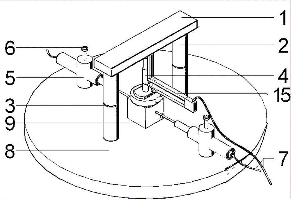
[0024] figure 1 It is a structural schematic diagram of the high-precision rock free expansion rate measuring device of the present invention, as figure 1 As shown, the bamboo-type high-precision rock free expansion rate measuring device provided by the present invention includes a chassis 8 on which two lateral displacement extensometers 5 and a movable and height-adjustable support are arranged. The bracket includes two height-adjustable pillars and a crossbea...


PUM

PropertyMeasurementUnit
diameteraaaaaaaaaa

Abstract

The invention discloses a bamboo joint type high-precision determination device for a free expansion ratio of rock. The determination device comprises six parts: an upper cross beam, a bamboo joint type bracket, coin-shaped strong magnets, a longitudinal displacement extensometer, a horizontal displacement extensometer and an irony chassis, wherein the upper cross beam is a common steel plate strip; the length of the upper cross beam is determined by the size of a tested sample; each bamboo joint type steel column has a 70mm height, 26mm outer diameter and 13.5mm inner diameter; and the coin-shaped strong magnets embedded in the bamboo joint have 2mm thicknesses and 19mm diameters. For the tested pieces different in size, users can easily adjust the height of vertical columns by increasing or reducing the quantity of the bamboo joint type steel columns and magnets; the two vertical columns are formed by sucking and sticking a plurality of bamboo joint type steel columns in same size to the magnets; the two vertical columns are firmly adsorbed on upper and lower metal plates; and the free expansion ratio of rock is tested through displacement convergence meters of the longitudinal displacement extensometer and the horizontal displacement extensometer. The determination device has the advantages of simple structure, freedom, flexibility, high precision and reliable performance.

Description

technical field [0001] The invention belongs to the technical field of rock physical and mechanical performance testing, in particular to a bamboo-type rock free expansion rate measuring device. Background technique [0002] The free expansion rate of rock is the percentage of the original diameter and height of the radial and axial deformation of the non-disintegrating rock sample after immersion in water. The traditional rock free expansion rate tester has a complex structure and has specific requirements for the shape and size of the rock sample. For example, it is generally required to process the rock sample to be tested into a cube or a cube (a cylinder with a diameter of 50-60mm and a height of about equal to the diameter; the side length of the cube is 50-60mm), and the two ends of the sample are required to be ground flat, and no matter whether wet processing or dry processing is used in the processing of standard test pieces, the original sample will be produced to...

Claims


Application Information

Patent Timeline
Patent Type & Authority Applications(China)
IPC IPC(8): G01N33/24
Inventor 马春德李光裕徐纪成曹志丰李夕兵曹万宝郭阳
Owner CENT SOUTH UNIV
Why Eureka
Try Eureka