Light source optimization method for adaptive photoetching system

A lithography system and light source optimization technology, which is applied in the direction of micro-lithography exposure equipment, photolithography exposure device, etc., can solve the problem of reducing the complexity of the light source pattern, taking a long time, and not considering the impact of light source simplification on the imaging performance of the lithography system And other issues

Active Publication Date: 2014-11-05
BEIJING INSTITUTE OF TECHNOLOGYGY
View PDF5 Cites 17 Cited by
  • Summary
  • Abstract
  • Description
  • Claims
  • Application Information

AI Technical Summary

Problems solved by technology

Therefore, the above method has the following two deficiencies: first, before optimizing the light source, this method must detect all key areas in the full-chip circuit pattern, and select observation points for all key areas, and then calculate the corresponding The complete ICC matrix of the observation point
Therefore, the newly added data of key areas and observation points will lead to a large amount of repeated optimization calculations
Second, the calculation complexity of the ICC matrix is ​​high and time-consuming, and this method must calculate the complete ICC matrix before the light source is optimized, so parallel computing cannot be used to simultaneously calculate the ICC matrix and optimize the light source, thus limiting The further improvement of the computational efficiency of the algorithm
However, this method does not consider the impact of light source simplification on the imaging performance of the lithography system while reducing the complexity of the light source pattern
Therefore, it is difficult to improve or maintain the imaging quality of the lithography system while reducing the complexity of the light source in the existing light source regularization method, which needs further improvement

Method used


Image

  • Light source optimization method for adaptive photoetching system
  • Light source optimization method for adaptive photoetching system
  • Light source optimization method for adaptive photoetching system

Examples


Embodiment

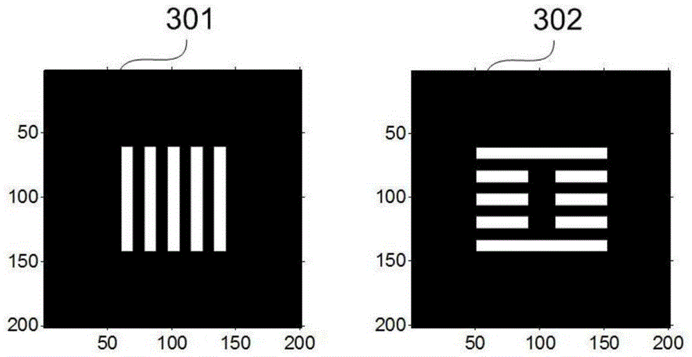
[0127] Such as image 3 Shown is a schematic diagram of two critical areas on the wafer, which are also target patterns, white represents the open area, black represents the light blocking area, and its critical dimension is 45nm. The lines in the key area indicated by 301 are along the vertical direction, and the lines in the key area indicated by 302 are along the horizontal direction.

[0128] Figure 4 is the initial light source graph, and the light source graph obtained after using the SELSE method to optimize the light source for the observation point data on the first key area. The initial light source shown in 401 is a ring light source; 402 is the result of optimizing the light source by using the SELSE method for the data of 2 observation points on the first key area; 403 is the result of optimizing the light source for 7 observations on the first key area The point data is the result of optimizing the light source by using the SELSE method; 404 is the result of o...


PUM


Abstract

The invention provides a light source optimization method for an adaptive photoetching system. The aims of optimizing a light source graph, improving the imaging property of the photoetching system and reducing the light source complexity as much as possible are achieved. The light source optimization method adopts a sequential least squares estimation method; the current light source graph is updated by adopting observation point data in a key region in each iteration; after all observation points are traversed, the light source graph is subjected to cyclic regularization by a reverse order recursive least squares estimation method. According to the method, if newly increased observation point data are acquired after light source optimization is finished, the current light source optimization result can be directly corrected, and a light source does not need to be re-optimized; meanwhile, the light source optimization method can realize parallel processing of illumination cross coefficient matrix calculation and light source optimization; furthermore, the complexity of the light source can be reduced, and the imaging quality of the photoetching system is improved or retained as much as possible; finally, with the adoption of a vector imaging model, a simulation precision requirement of a high-NA photoetching system can be met.

Description

technical field [0001] The invention relates to a light source optimization method for an adaptive lithography system using sequential least square estimator (SELSE for short) and order-recursive least square estimator (ORLSE for short), The invention belongs to the technical field of photolithography resolution enhancement. Background technique [0002] The current very large-scale integrated circuits are mainly manufactured by the 193nm ArF deep ultraviolet lithography system. With the continuous reduction of the critical dimension (CD) of integrated circuits and the continuous improvement of integration, resolution enhancement technology must be adopted. (resolution enhancement technique, RET for short) improves the imaging resolution and graphic fidelity of the lithography system. Source optimization (SO for short) is an important technique for enhancing the resolution of lithography. The SO technology optimizes the light intensity distribution of the light source and ...

Claims


Application Information

Patent Timeline
Patent Type & Authority Applications(China)
IPC IPC(8): G03F7/20
Inventor 马旭高杰陈譞博李艳秋
Owner BEIJING INSTITUTE OF TECHNOLOGYGY
Why Eureka
Try Eureka