Temperature control device for refining metal solidification structure by use of pulse current

A temperature control device, metal solidification technology, applied in the direction of temperature control, non-electric variable control, control/regulation system, etc., can solve the problem of lack of precise control and measurement records of molten metal temperature, and achieve controllability and controllability Repeatability, simple operation, automatic collection and storage

Active Publication Date: 2014-11-05
KUNMING UNIV OF SCI & TECH
View PDF5 Cites 5 Cited by
  • Summary
  • Abstract
  • Description
  • Claims
  • Application Information

AI Technical Summary

Problems solved by technology

[0005] In order to solve the problem of the lack of precise control and measurement records of the temperature of the metal melt in the process of refining the metal solidification structure with pulse current under the heating of the existing tubular resistance furnace, a method suitable for the refinement of metal solidification with pulse current under the heating of the tube furnace is provided. The control device for the temperature of the molten metal and the temperature of the furnace during the organization process, the device includes the temperature measuring thermocouple Ⅰ1, the temperature measuring thermocouple Ⅱ2, the temperature measuring thermocouple Ⅲ3, the heat insulation asbestos 4, the tubular resistance furnace body Ⅰ5, and the ceramic support Tube 6, heat-resistant ceramic tube Ⅰ 7, air outlet 8, water glass sand Ⅰ 9, electrode 10, compensation wire Ⅰ 11, water glass sand Ⅱ 12, heat-resistant ceramic tube Ⅱ 13, tubular resistance furnace body Ⅱ 14, high-voltage pulse power supply 15, inlet Air hole 17, temperature control and data acquisition device 18, compensation wire II19, compensation wire III20, compensation wire IV21, displacement and guiding device I22, displacement and guiding device II23, displacement and guiding device III24, temperature measuring thermocouple I1, temperature measuring Thermocouple Ⅱ2 and temperature measuring thermocouple Ⅲ3 are respectively installed on displacement and guiding device Ⅰ22, displacement and guiding device Ⅱ23, displacement and guiding device Ⅲ24, and displacement and guiding device Ⅰ22, displacement and guiding device Ⅱ23, and displacement and guiding device Ⅲ24 respectively pass through Compensation wire II19, compensation wire III20, compensation wire IV21 are connected to temperature control and data acquisition device 18; displacement and guiding device I22, displacement and guiding device II23, displacement and guiding device III24 are vertically installed on heat-insulating asbestos 4, and heat-insulating Asbestos 4 is located at the upper end of the tubular resistance furnace body I5, ceramic support tubes 6 are placed on both sides of the tubular resistance furnace body I5, and heat-resistant ceramic tubes I7 are fixed on the ceramic support tubes 6 on both sides of the tubular resistance furnace body I5 , the heat-resistant ceramic tube II13 is located inside the heat-resistant ceramic tube I7, the electrode 10 passes through the heat-resistant ceramic tube I7 and the heat-resistant ceramic tube II13, and is connected to the high-voltage pulse power supply 15 through the wire I11, the heat-resistant ceramic tube I7 and the heat-resistant ceramic tube The two ends of the tube II13 are sealed with water glass sand I9 and water glass sand II12 respectively; the two ends of the heat-resistant ceramic tube I7 are respectively provided with an air outlet 8 and an air inlet 17

Method used


Image

  • Temperature control device for refining metal solidification structure by use of pulse current
  • Temperature control device for refining metal solidification structure by use of pulse current
  • Temperature control device for refining metal solidification structure by use of pulse current

Examples


Embodiment 1

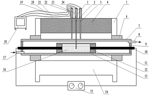
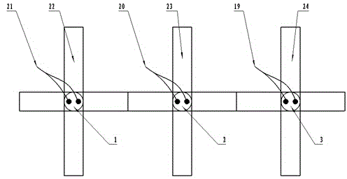
[0022]The temperature control device used for pulse current refinement of metal solidification structure described in this embodiment, the device includes temperature measuring thermocouple I1, temperature measuring thermocouple II2, temperature measuring thermocouple III3, heat insulating asbestos 4, tubular resistance furnace Body Ⅰ5, ceramic support tube 6, heat-resistant ceramic tube Ⅰ7, air outlet 8, water glass sand Ⅰ9, electrode 10, compensation wire Ⅰ11, water glass sand Ⅱ12, heat-resistant ceramic tube Ⅱ13, tubular resistance furnace body Ⅱ14, high pressure Pulse power supply 15, air intake hole 17, temperature control and data acquisition device 18, compensation wire II19, compensation wire III20, compensation wire IV21, displacement and guiding device I22, displacement and guiding device II23, displacement and guiding device III24, thermoelectricity measurement Couple I1, temperature measuring thermocouple II2, and temperature measuring thermocouple III3 are installe...

Embodiment 2

[0027] The device includes temperature measuring thermocouple Ⅰ1, temperature measuring thermocouple Ⅱ2, temperature measuring thermocouple Ⅲ3, heat insulation asbestos 4, tubular resistance furnace body Ⅰ5, ceramic support tube 6, heat-resistant ceramic tube Ⅰ7, air outlet 8, water Glass sand I9, electrode 10, compensation wire I11, water glass sand II12, heat-resistant ceramic tube II13, tubular resistance furnace body II14, high-voltage pulse power supply 15, air inlet 17, temperature control and data acquisition device 18, compensation wire Ⅱ19, compensation wire Ⅲ20, compensation wire Ⅳ21, displacement and guiding device Ⅰ22, displacement and guiding device Ⅱ23, displacement and guiding device Ⅲ24, temperature measuring thermocouple Ⅰ1, temperature measuring thermocouple Ⅱ2, and temperature measuring thermocouple Ⅲ3 are respectively installed in the displacement and guiding device On the guide device I22, the displacement and guide device II23, and the displacement and gui...

Embodiment 3

[0033] The temperature control device used for pulse current refinement of metal solidification structure described in this embodiment, the device includes temperature measuring thermocouple I1, temperature measuring thermocouple II2, temperature measuring thermocouple III3, heat insulating asbestos 4, tubular resistance furnace Body Ⅰ5, ceramic support tube 6, heat-resistant ceramic tube Ⅰ7, air outlet 8, water glass sand Ⅰ9, electrode 10, compensation wire Ⅰ11, water glass sand Ⅱ12, heat-resistant ceramic tube Ⅱ13, tubular resistance furnace body Ⅱ14, high pressure Pulse power supply 15, air intake hole 17, temperature control and data acquisition device 18, compensation wire II19, compensation wire III20, compensation wire IV21, displacement and guiding device I22, displacement and guiding device II23, displacement and guiding device III24, thermoelectricity measurement Couple I1, temperature measuring thermocouple II2, and temperature measuring thermocouple III3 are install...


PUM


Abstract

The invention discloses a temperature control device for refining a metal solidification structure by use of pulse current, and belongs to the field of metal solidification control. The temperature control device mainly comprises temperature measurement thermocouples, a temperature control and data acquisition device, and displacement and guiding devices. The device is mainly characterized in that the process temperature is controlled and measured when a metal melt is processed by use of pulse current. The temperature measurement thermocouples measure the temperature of a metal melt in real time, and the temperature control and recording device controls the temperature of the metal melt and acquires data of the temperature. The device has outstanding advantages in application of metal melt processing by pulse current under heating of a tubular resistance furnace. By adopting the device, the temperature of a metal melt can be measured accurately, operation is simple, the error is small, and the influence of pulse current to the process of metal solidification can be analyzed based on acquired data. The device has positive significance to accurate control of metal melt temperature and controllability of the processing process during metal solidification structure refining by use of pulse current.

Description

technical field [0001] The invention relates to a temperature control device for refining metal solidification structure with pulse current, belonging to the field of metal solidification control. Background technique [0002] In the field of material science and technology, the control of metal solidification process is an important way to improve the performance of metal materials and develop new materials. With the rapid development of modern science and technology, people's requirements for material properties are constantly improving. Therefore, the electric current solidification technology has gradually become a research hotspot in refining and improving the solidification structure of metals. Current coagulation technology is a method of applying a certain current, such as alternating current, direct current or pulse current (Electric Current Pulse, ECP), etc., during the solidification process or liquid state of the metal, so as to refine the solidified structure of...

Claims


Application Information

Patent Timeline
Patent Type & Authority Applications(China)
IPC IPC(8): G05D23/22
Inventor 周荣锋吕海洋陈华蒋业华周荣
Owner KUNMING UNIV OF SCI & TECH
Why Eureka
Try Eureka