Insulated electric cable
A technology for electrical insulation and wires, applied in the direction of insulated cables, insulated conductors, cables, etc., can solve the problems of reduced workability, reduced adhesion, powder scattering, etc., and achieves good workability
- Summary
- Abstract
- Description
- Claims
- Application Information
AI Technical Summary
Problems solved by technology
Method used
Image

Examples
no. 1 Embodiment approach
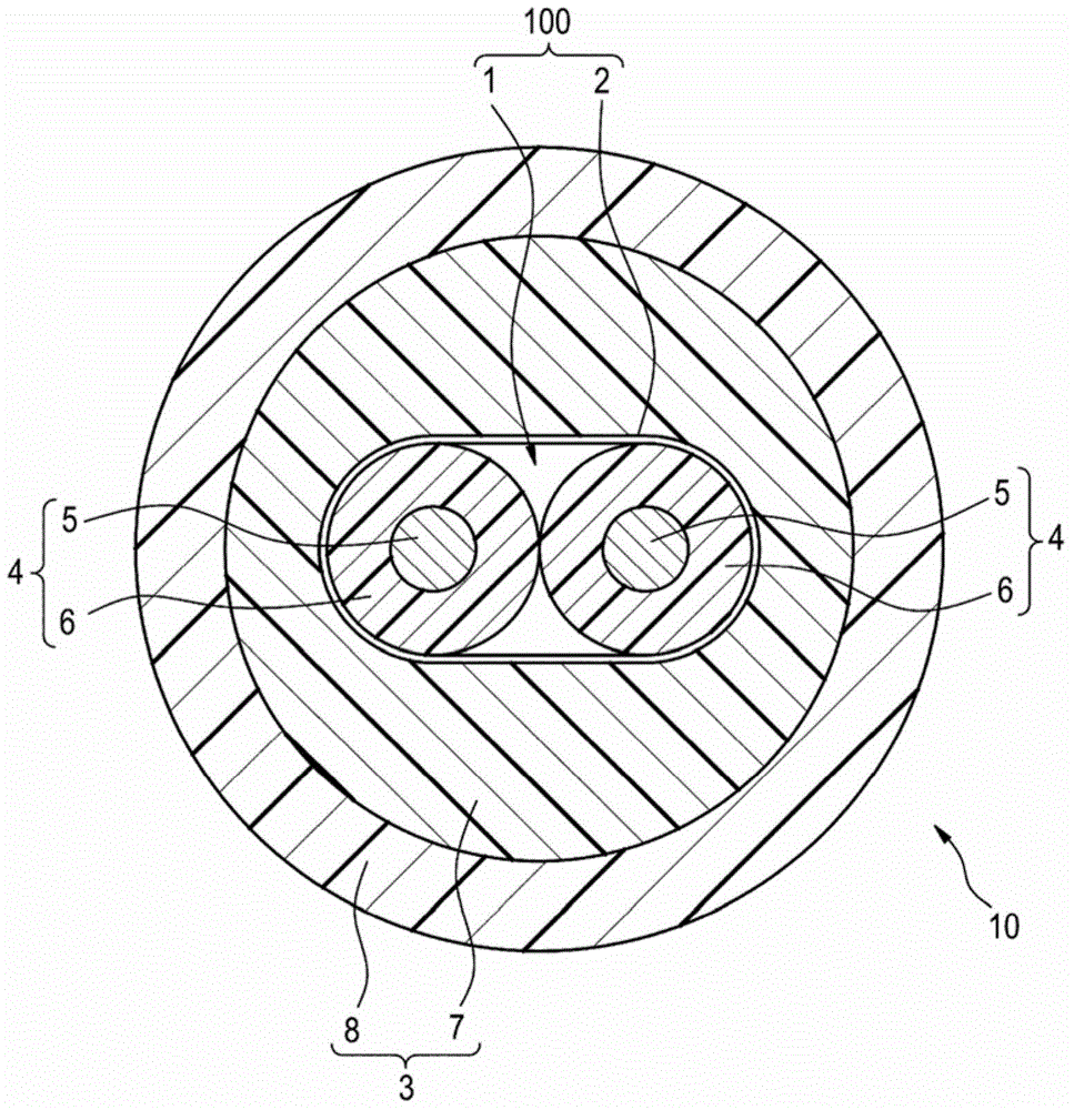
[0047] figure 1 It is a cross-sectional view showing the structure of the electrically insulating cable 10 according to the first embodiment of the present invention. The electrically insulated cable 10 is used, for example, in an electric parking brake (Electro Mechanical Parking Brake: EPB) mounted on a vehicle, and can be used as a cable that transmits an electric signal to a motor that drives a brake caliper. .
[0048] Such as figure 1 As shown, an electrically insulated cable 10 has: a core material 1; a paper tape 2 (an example of a tape member) wound on the core material 1; and a sheath 3 covering the paper wound on the core material 1. The outer periphery of the band 2 is covered. The outer diameter of the electrically insulated cable 10 of this example is set within a range of 6 to 12 mm, preferably within a range of 8.3 to 10.3 mm.
[0049] The core material 1 is formed by twisting two first core electric wires 4 (an example of core electric wires), and the two ...
no. 2 Embodiment approach
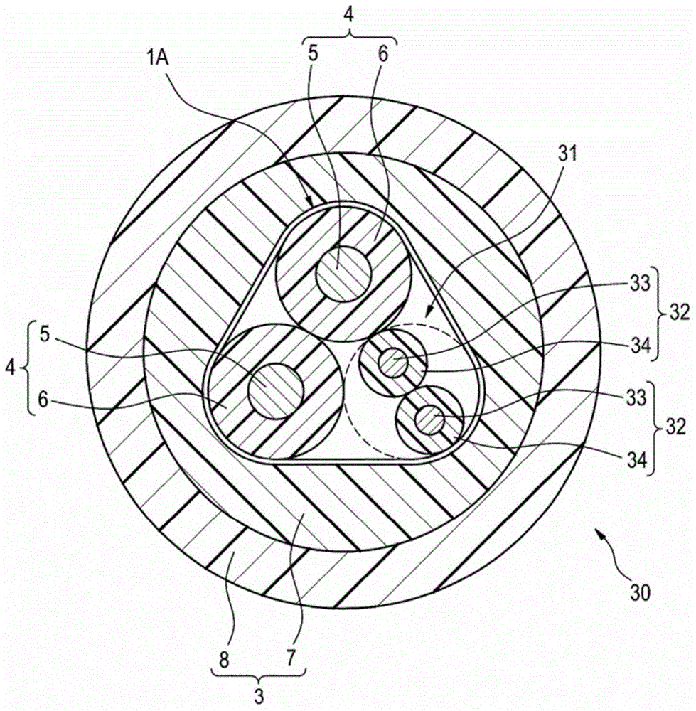
[0064] Below, refer to image 3 A second embodiment of the present invention will be described. In addition, the same code|symbol is attached|subjected to the part with the same structure as 1st Embodiment, and description is abbreviate|omitted. image 3 A cross section of the electrically insulating cable 30 according to the second embodiment is shown. The electrically insulated cable 30 of this example can also be used to transmit electrical signals for controlling the operation of an anti-lock brake system (Antilock Brake System: ABS) in addition to the use for transmitting electrical signals of an electric parking brake.
[0065] Such as image 3 As shown, the electrically insulated cable 30 of this example differs from the first embodiment in that the core material 1A includes a subunit 31 for transmitting ABS signals in addition to the two first core wires 4 .
[0066] The subunit 31 is formed by twisting two second core electric wires 32 (an example of core electric ...
Embodiment 1
[0075]As an electrically insulated cable (for EPB) for a test, a cable having the following structures in each part was produced. The material of the conductor constituting the first core electric wire is a copper alloy wire (a double-stranded wire formed by twisting 52 base wires with an outer diameter of 0.08mm to form a twisted wire, and twisting seven of the twisted wires) Line), the cross-sectional area of the conductor (the total cross-sectional area of the baseline) is set to 1.8mm 2 , the outer diameter is set to 2.0mm. In addition, the material of the insulating layer formed around the conductor was flame-retardant cross-linked polyethylene, the thickness of the insulating layer was 0.4 mm, and the outer diameter was 2.8 mm. In addition, the number of core electric wires (first core electric wires) constituting the core material was set to two, and the stranding diameter (outer diameter in the twisted state) was set to 5.6 mm. In addition, as the structure of th...
PUM
| Property | Measurement | Unit |
|---|---|---|
| thickness | aaaaa | aaaaa |
| thickness | aaaaa | aaaaa |
Abstract
Description
Claims
Application Information
 - R&D
- Intellectual Property
- Life Sciences
- Materials
- Tech Scout
- Unparalleled Data Quality
- Higher Quality Content
- 60% Fewer Hallucinations
Browse by: Latest US Patents, China's latest patents, Technical Efficacy Thesaurus, Application Domain, Technology Topic, Popular Technical Reports.
© 2025 PatSnap. All rights reserved.Legal|Privacy policy|Modern Slavery Act Transparency Statement|Sitemap|About US| Contact US: help@patsnap.com