Conductive slip ring

A conductive slip ring and conductive ring technology, applied in the direction of circuits, current collectors, electrical components, etc., can solve problems such as voice out of sync, unstable work, expensive prices, etc., to achieve the effect of ensuring stability and good contact

Active Publication Date: 2014-11-05
DONGGUAN TECONN ELECTRONICS TECH CO LTD
View PDF6 Cites 3 Cited by
  • Summary
  • Abstract
  • Description
  • Claims
  • Application Information

AI Technical Summary

Problems solved by technology

[0003] In the process of digital high-definition signal transmission, conductive slip rings are the key components for power and signal transmission. Due to their harsh working environment, long service life, and long-term rotational movement, the performance requirements for slip rings are very strict. Such products have long relied on imported, expensive
Domestic slip rings work unstable in harsh environments, and are prone to problems such as signal delay, voice out-of-sync, and data signal loss, which is not conducive to popularization and application

Method used


Image

  • Conductive slip ring
  • Conductive slip ring
  • Conductive slip ring

Examples


Embodiment Construction

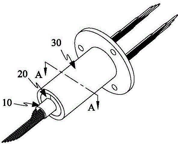
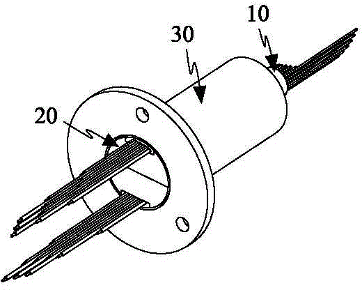
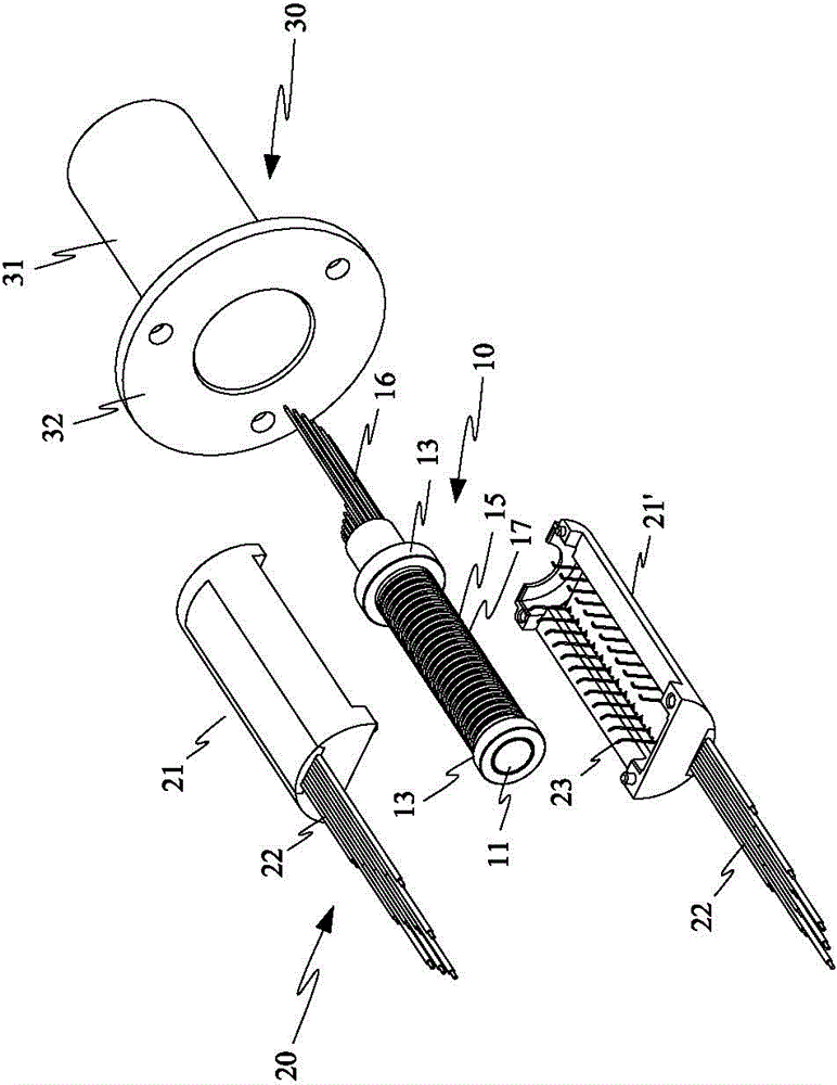
[0068] Please refer to Figure 1 to Figure 4 As shown, it shows the specific structure of the preferred embodiment of the present invention, the conductive slip ring includes a rotor assembly 10, a stator assembly 20 and a casing 30, the stator assembly 20 wraps the rotor assembly 10, and the casing 30 It is sleeved on the outside of the stator assembly 20 . By making the rotor assembly 10 rotate relative to the stator assembly 20, signal transmission is realized, which solves the problem that the traditional straight-through cable transmission cannot rotate and twist.

[0069] Among them, such as Figure 4 to Figure 20 As shown, the rotor assembly 10 includes a shaft core 11 , a distribution disc 12 , two bearings 13 , a sealing cover 14 , several conductive rings 15 and several inner ring wires 16 .

[0070] Such as Figure 15 As shown, the shaft core 11 has a cylindrical central shaft body 111 and a blocking piece 112 integrally formed at the tail end of the central shaf...


PUM


Abstract

The invention discloses a conductive slip ring which comprises a rotor assembly, a stator assembly and a housing, wherein the stator assembly covers the rotor assembly; and the housing is arranged outside the stator assembly in a sleeving manner. The rotor assembly rotates relative to the stator assembly, so that signal transmission is achieved, and the problem of incapable rotation and twisting of the traditional through-type cable during transmission is solved. The rotor assembly comprises a shaft core, a distributing board, a plurality of conductive rings and a plurality of inner ring leads, wiring grooves are uniformly formed axially at the periphery of the shaft core, and limiting grooves are uniformly formed at the periphery of the distributing board, so that the inner ring leads are distributed in the wiring grooves and the limiting grooves in a one-to-one correspondence manner. Wiring is very concise and easy; disalignment does not exist after wiring; looseness is not easy; positioning is good; stable signal transmission is ensured; next assembling and forming are facilitated; the assembling time is saved greatly; and the assembling efficiency is improved.

Description

technical field [0001] The invention relates to a technology in the field of slip rings, in particular to an ultra-high-speed, high-current conductive slip ring. Background technique [0002] Conductive slip ring belongs to the application category of electrical contact sliding connection. A precision power transmission device for image, data signal and power transmission of a relative rotating mechanism. It is especially suitable for applications where unlimited continuous rotation is required, and at the same time power or data needs to be transmitted from a fixed position to a rotating position. It is a key component of various precision turntables, centrifuges and inertial navigation equipment. [0003] In the process of digital high-definition signal transmission, conductive slip rings are the key components for power and signal transmission. Due to their harsh working environment, long service life, and long-term rotational movement, the performance requirements for ...

Claims


Application Information

Patent Timeline
IPC IPC(8): H01R39/08
Inventor 孙鸿运李胡彬
Owner DONGGUAN TECONN ELECTRONICS TECH CO LTD
Why Eureka
Try Eureka