Device and method of generating high-speed picosecond narrow pulse laser

A narrow pulse and laser technology, applied in the direction of excitation methods/devices, lasers, laser components, etc., can solve the problems of complex realization and technical difficulties in single photon source realization, and achieve stable output power, simple structure and small volume Effect

Inactive Publication Date: 2014-11-05
ANHUI QASKY QUANTUM SCI & TECH CO LTD
View PDF3 Cites 16 Cited by
  • Summary
  • Abstract
  • Description
  • Claims
  • Application Information

AI Technical Summary

Problems solved by technology

Single-photon sources are usually used as quantum light, but the real single-photon source technology is very difficult, and currently only weakly coherent light can be used to replace single-photon sources
The disadvantage of w...

Method used


Image

  • Device and method of generating high-speed picosecond narrow pulse laser
  • Device and method of generating high-speed picosecond narrow pulse laser

Examples


Embodiment 1

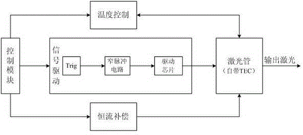
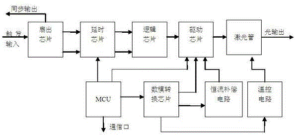
[0015] see figure 1 and figure 2 , the device for generating high-speed picosecond narrow pulse laser, including a control module, a signal drive module, a constant current compensation module, a temperature control module and a laser tube; the laser tube has its own TEC; the control module is connected with the signal drive module, The constant current compensation module and the temperature control module are electrically connected; the signal drive module, the constant current compensation module, and the temperature control module are respectively electrically connected to the laser tube; the control module converts the input trigger signal into a radio frequency drive through the signal drive module signal and output the radio frequency driving signal to the laser tube to drive the laser to work and output laser at a constant temperature; the control module controls the working temperature of the laser tube through the temperature control module so that the laser works a...

Embodiment 2

[0017] see figure 1 and figure 2, the method for generating a high-speed picosecond narrow pulse laser comprises the following steps: 1) outputting a radio frequency driving signal: the control module outputs a control signal to the signal driving module, and the signal driving module converts the input trigger signal into a radio frequency driving signal according to the control signal and Output the RF drive signal to the laser tube to drive the laser to work and output laser at a constant temperature. The laser tube has its own Tec; 2) Temperature control: At the same time as step 1), the control module also passes the temperature control module Control the working temperature of the laser tube to make the laser work at a constant temperature; 3) Constant current compensation: at the same time as step 1), the control module controls the magnitude of the compensation current through the constant current compensation module, so that the laser is a constant current output . ...


PUM


Abstract

The invention discloses a device of generating high-speed picosecond narrow pulse laser. A control module is electrically connected with a signal driving module, a constant current compensation module and a temperature control module respectively; the signal driving module, the constant current compensation module and the temperature control module are electrically connected with a laser tube; the control module converts an input triggering signal into a radio frequency driving signal by the signal driving module, and outputs the radio frequency driving signal to the laser tube to drive a laser device to work at a constant temperature to output laser; the control module controls the working temperature of the laser tube by the temperature control module to allow the laser device to work at a constant temperature; and the control module controls the magnitude of compensation current by the constant current compensation module to allow the laser device to output at constant current. The invention further discloses a method of generating the high-speed picosecond narrow pulse laser. The device is stable in output, can be suitable for a quantum key distribution system with quantum light and synchronous light multiplexing an optical fiber, and has the characteristics of concision, convenience and low cost.

Description

[0001] technical field [0002] The invention relates to a pulse generating device and method for generating quantum light and synchronous light in the field of quantum encryption communication, in particular to a device and method for generating high-speed picosecond narrow pulse laser. Background technique [0003] At present, picosecond lasers below 1 GHz are relatively mature, and there are already commercial products in the world. The operating frequency of the 10ps order pulse laser of Germany Advanced Laser Diode is 10MHz; the operating frequency of the 20ps laser of Japan HAMAMATSU is 100MHz; the operating frequency of the Swiss IDQ pulse laser is 500MHz. The operating frequency of the device can reach 1GHz, the minimum pulse width can reach the order of 50ps, and the performance is far superior to existing products. [0004] The quantum key distribution system is based on the unclonability and uncertainty of quantum, which makes the quantum key distribution system ...

Claims


Application Information

Patent Timeline
IPC IPC(8): H01S3/02H01S3/09H01S3/10H01S3/11
Inventor 吕利影苗春华刘云宋晨赵义博韩正甫
Owner ANHUI QASKY QUANTUM SCI & TECH CO LTD
Why Eureka
Try Eureka