
Well drilling tool mud scraping device

A drilling tool and drilling technology, used in cleaning tools, earthwork drilling, wellbore/well components, etc., can solve the problems of increasing difficulty and complexity, reducing mud scraping effect of drill pipe, and reducing work reliability, etc. Effectiveness and reliability, saving labor time, improving the effect of mud scraping

Active Publication Date: 2014-11-12
JIANGSU YANGZHOU HELI RUBBER PROD
View PDF6 Cites 0 Cited by
  • Summary
  • Abstract
  • Description
  • Claims
  • Application Information

AI Technical Summary

Problems solved by technology

[0004] 1) The operation is complicated. For example, when passing a large-diameter drill pipe joint, it is necessary to lift the scraper frame upwards for operation, resulting in cumbersome operation and reducing the reliability of the work; moreover, it requires several workers to cooperate with lifting the scraper frame to operate, which increases the Difficulty and complexity, if the cooperation is not good, continue to cooperate until the coordination and pace are consistent; increase the working time;
[0005] 2) Poor adaptability, it is necessary to replace mud scrapers of different specifications in order to adapt to the mud scraping operation of various drill pipes, which increases labor time
[0006] At the same time, when there is an adaptive drill pipe mud scraper, such as Figure 21 As shown, in normal operation, the mud scraper and the drill pipe 131 are in close contact; as Figure 22-23 As shown, in operation, as the diameter of the drill pipe (drill pipe 2 132 and drill pipe 3 133) becomes smaller, the adaptive effect of the drill pipe mud scraper is very poor, due to the change and deformation of the curvature of the arc-shaped rubber flap Features, the phenomenon that the middle fits and the two ends cannot fit, which reduces the effect of drill pipe mud scraping

Method used


Image

  • Well drilling tool mud scraping device
  • Well drilling tool mud scraping device
  • Well drilling tool mud scraping device

Examples


Embodiment Construction

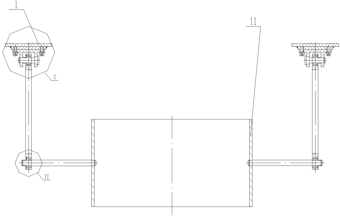
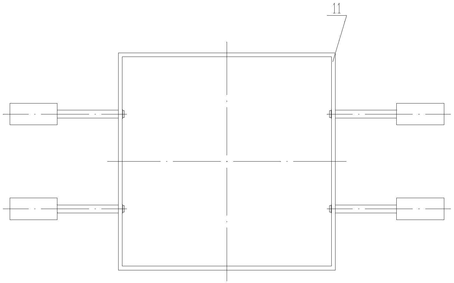
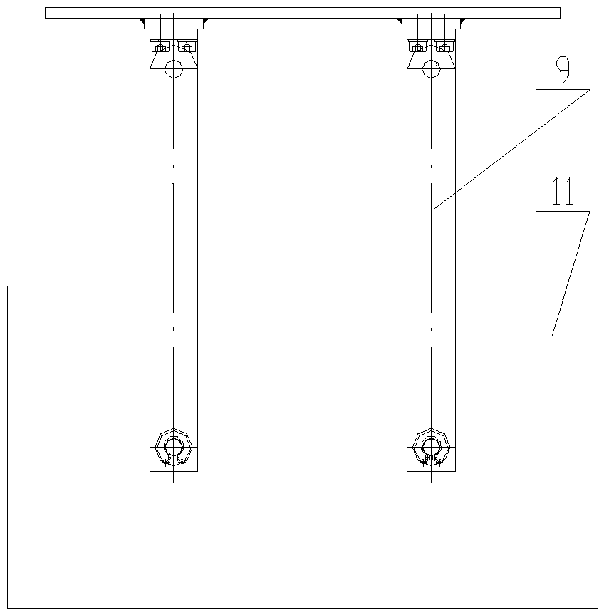
[0064] The present invention as Figure 1-20 As shown, including the universal lifting device and the mud scraper of the drilling tool,

[0065] The universal hoisting device includes a cylinder body 11 and a pair of swing rod assemblies. The swing rod assemblies are respectively connected to the lower part of the drill platform 1, so that the cylinder 11 swings relative to the drill platform;

[0066] The drilling tool mud scraper is arranged in the cylinder body 11, and the drilling tool mud scraper includes an upper mud scraping group and a lower mud scraping group, and the upper mud scraping group is located above the lower mud scraping group;

[0067] The upper mud scraping group and the lower mud scraping group respectively include a pair of mud scraping assemblies 12 arranged oppositely,

[0068] The mud scraping assembly 12 includes an inflatable mud scraping flap 121, a steel ring 122, a swing cylinder 123, a rotating shaft 124, a fixed seat 125, a swing...


PUM


Abstract

The invention provides a well drilling tool mud scraping device which is simple in structure, convenient to operate and capable of effectively improving working efficiency and reliability. The well drilling tool mud scraping device comprises a universal hoisting device and a drilling tool mud scraper. The universal hoisting device comprises a barrel body and a pair of oscillating rod assemblies. The barrel body is in a square shape. The oscillating rod assemblies are symmetrically arranged on the two sides of the barrel body respectively. The oscillating rod assemblies are respectively connected to the lower portion of a drilling rod platform, so that the barrel body oscillates relative to the drilling rod platform. The drilling tool mud scraper is arranged in the barrel body and comprises an upper mud scraper set and a lower mud scraper set. Each mud scraper assembly comprises an inflation mud scraper piece, a steel ring, an oscillating cylinder, a rotating rod, a fixed base, an oscillating rod and an air source, wherein the inflation mud scraper piece is in a circular arc shape, is fixedly connected to the steel ring and is provided with an air hole, and the air source is communicated with the air hole. According to the well drilling tool mud scraping device, working efficiency is improved, and the labor intensity of oil workers is relieved.

Description

technical field [0001] The invention relates to a drilling tool mud scraping device in drilling operation. Background technique [0002] During drilling operations in oil fields, mud adheres to the drill pipe, which affects the work of the drill pipe. At the same time, if the mud on the drill pipe is taken out to the drilling platform, it will seriously affect the working environment; therefore, it is very necessary to remove the drill pipe. Mud on the pole. [0003] The announcement number authorized by the State Intellectual Property Office on July 12, 2006 is CN2795439Y, and the patent title is "a kind of mud scraper". It is equipped with two sets of upper and lower mud scraper devices in the open barrel, which can effectively and automatically scrape the drill pipe The mud on the surface can reduce the labor intensity of oil workers; however, there are the following problems in the working process: [0004] 1) The operation is complicated. For example, when passing a l...

Claims


Application Information

Patent Timeline
Patent Type & Authority Applications(China)
IPC IPC(8): E21B37/02
Inventor 张善德朱克斌安青龙高元姚玉娟袁建东翁兰芳
Owner JIANGSU YANGZHOU HELI RUBBER PROD
Learn More