
Transmission insulator and isolating switch using same

A technology of isolating switches and insulators, applied in the direction of air switch parts and other directions, can solve the problems of the breakdown of the partition body, the decline of the reliability of the rotating insulator, the decline of the anti-breakdown performance of the shaft sleeve inserts and the threaded sleeve inserts, etc. Achieve compact structure, ensure reliability and reduce distance

Active Publication Date: 2014-11-12
STATE GRID CORP OF CHINA +2
View PDF6 Cites 7 Cited by
  • Summary
  • Abstract
  • Description
  • Claims
  • Application Information

AI Technical Summary

Problems solved by technology

[0003] The Chinese patent with the notification number CN202394790U discloses a rotating insulator. The rotating insulator includes an insulating base, a threaded sleeve insert, a shaft sleeve insert and a drive disk. The shaft sleeve insert is petal-shaped, and the threaded sleeve insert is located on the shaft sleeve Between the petal gaps of the parts, the number of threaded sleeve inserts is the same as the number of petals of the shaft sleeve inserts, and they are at different potentials from the shaft sleeve inserts, and the drive disc is fixed on the threaded sleeve inserts through screw connections. When in use, the two transmission shafts that need to be connected by transmission are respectively anti-rotation inserted on the sleeve insert and the drive plate, so as to realize the transmission connection between the two transmission shafts through the rotating insulator, but because the transmission shaft is driving the rotating insulator to rotate During the process, the transmission shaft will apply a circumferential torque around the rotation axis to the rotating insulator, and this part of the torque will act between the adjacent threaded inserts on the rotating insulator and the petals of the sleeve insert, so in the transmission During the rotation of the shaft, the partition entities of the petals of the adjacent threaded sleeve inserts and the shaft sleeve inserts will be compressed and deformed, so that the anti-puncture performance between the shaft sleeve inserts and the threaded sleeve inserts will be reduced, especially at high pressure In the electrical control mechanism, the partition entity between the shaft sleeve insert and the threaded sleeve insert is prone to breakdown, resulting in a decrease in the reliability of the rotating insulator

Method used


Image

  • Transmission insulator and isolating switch using same
  • Transmission insulator and isolating switch using same
  • Transmission insulator and isolating switch using same

Examples


Embodiment Construction

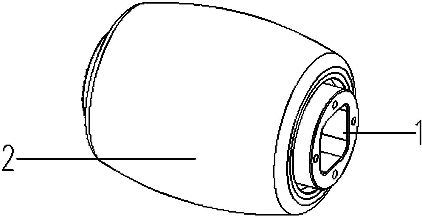
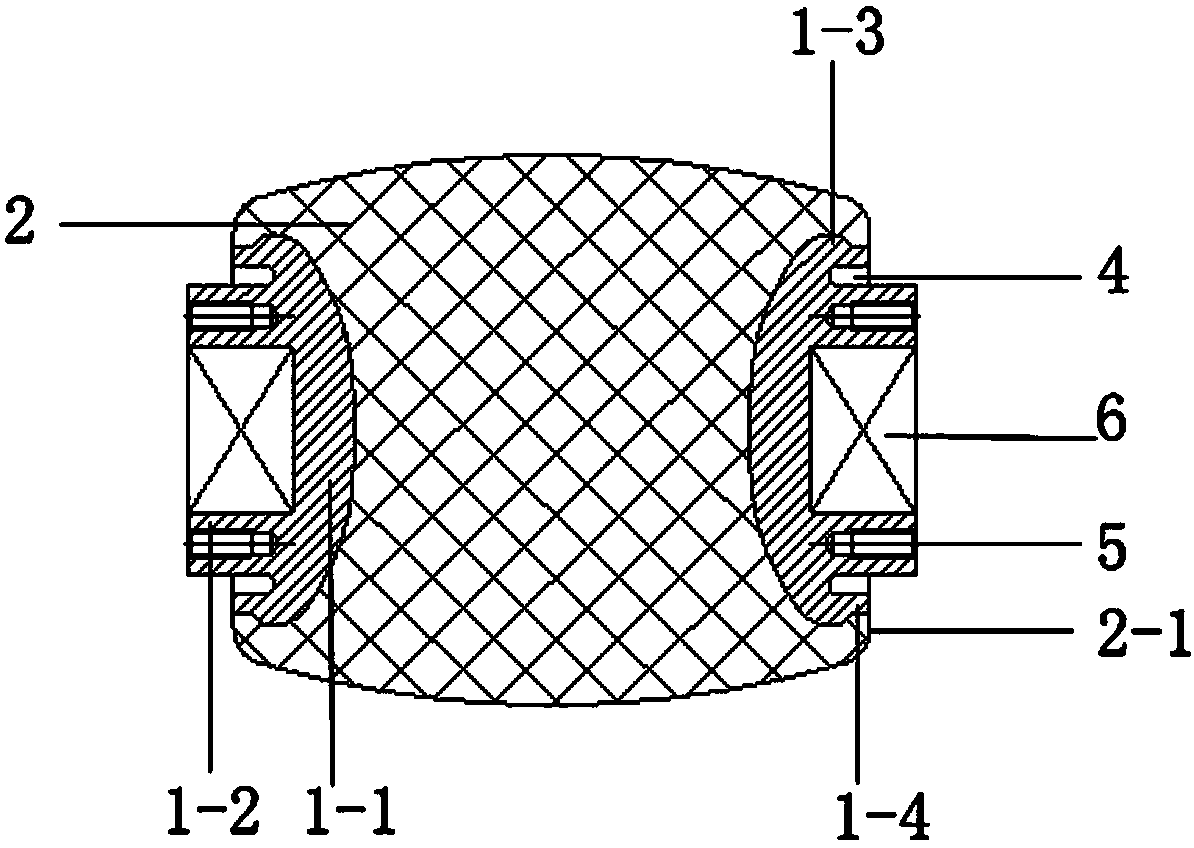
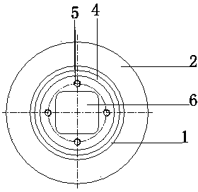
[0023] Embodiments of the isolating switch of the present invention: as Figure 1 to Figure 4 As shown, the isolating switch of this embodiment is a three-position isolating and grounding switch of a gas-insulated metal-enclosed switchgear (GIS for short). The transmission shaft 20 and the transmission insulator 30, the transmission insulator 30 is coaxially connected between the output transmission shaft 10 and the interphase transmission shaft 20 and between two adjacent transmission shafts, and the transmission insulator 30 is composed of a drum-shaped insulating base 2 and an insulating base 2 The sleeve insert 1 embedded at both ends is composed of the outer peripheral surface of the insulating base 2 which is a drum-shaped surface of revolution that gradually becomes thinner from the abdomen to both ends in the axial direction, and the inner end of the sleeve insert 1 is embedded and fixed on the insulation The embedded end 1-1 and the outer end in the matrix 2 are expos...


PUM


Abstract

The invention discloses a transmission insulator and an isolating switch using the same. The embedding ends of two shaft sleeve inserts of the transmission insulator are distributed in a relatively spaced mode in the rotating axis direction of an insulation base body which is provided with an insolating solid object isolating the two shaft sleeve inserts on the rotating axis. Due to the fact that the embedding ends of the two shaft sleeve inserts are distributed in the relatively spaced mode in the rotating axis direction of the insulation base body, when the transmission insulator is driven to rotate by a transmission shaft, the direction of torque borne by the two shaft sleeve inserts is perpendicular to the isolating direction between the two shaft sleeve inserts, and the problem that the isolating solid object between the two shaft sleeve inserts is compressed, and the thickness of the isolating solid object (equivalent to an insulation medium in a capacitor) between the two shaft sleeve inserts is reduced is solved. The hidden danger that the isolating solid object between the two shaft sleeve inserts is broken down is lowered, and the using reliability of the transmission insulator is ensured.

Description

technical field [0001] The invention relates to a disconnector in a gas-insulated metal-enclosed switchgear (GIS for short) and a transmission insulator used in the disconnector. Background technique [0002] At present, in gas-insulated metal-enclosed switchgear (GIS for short) products, insulators play an important role in supporting conductors, torque transmission and insulation. It is specifically manifested in the process of closing action and opening action, the output torque of the operating mechanism, and then through the interphase transmission insulator that acts as a transmission connection between the torque output shaft of the operating mechanism and the corresponding phase shaft and between the adjacent two phase shafts. It is realized by driving the three-phase moving contacts to rotate synchronously. The existing interphase transmission insulators use insulating rubber-soaked tubes, and the transmission is connected by shaft pins. This transmission connection...

Claims


Application Information

Patent Timeline
IPC IPC(8): H01H31/02
Inventor 薛红涛黄坤鹏方煜瑛石治中李七军
Owner STATE GRID CORP OF CHINA
Features
  • Generate Ideas
  • Intellectual Property
  • Life Sciences
  • Materials
  • Tech Scout
  • Unparalleled Data Quality
  • Higher Quality Content
  • 60% Fewer Hallucinations
Learn More