

Embedded permanent magnet rotary electric machine
A technology of rotating electrical machines and permanent magnets, which is applied to synchronous motors with stationary armatures and rotating magnets, magnetic circuit rotating parts, electric components, etc., and can solve the problems of less cooling air volume and inability to effectively cool permanent magnets , to achieve the effects of suppressing temperature rise, improving performance, and reducing ventilation resistance
- Summary
- Abstract
- Description
- Claims
- Application Information
AI Technical Summary
Problems solved by technology
Method used
Image

Examples
Embodiment approach 1
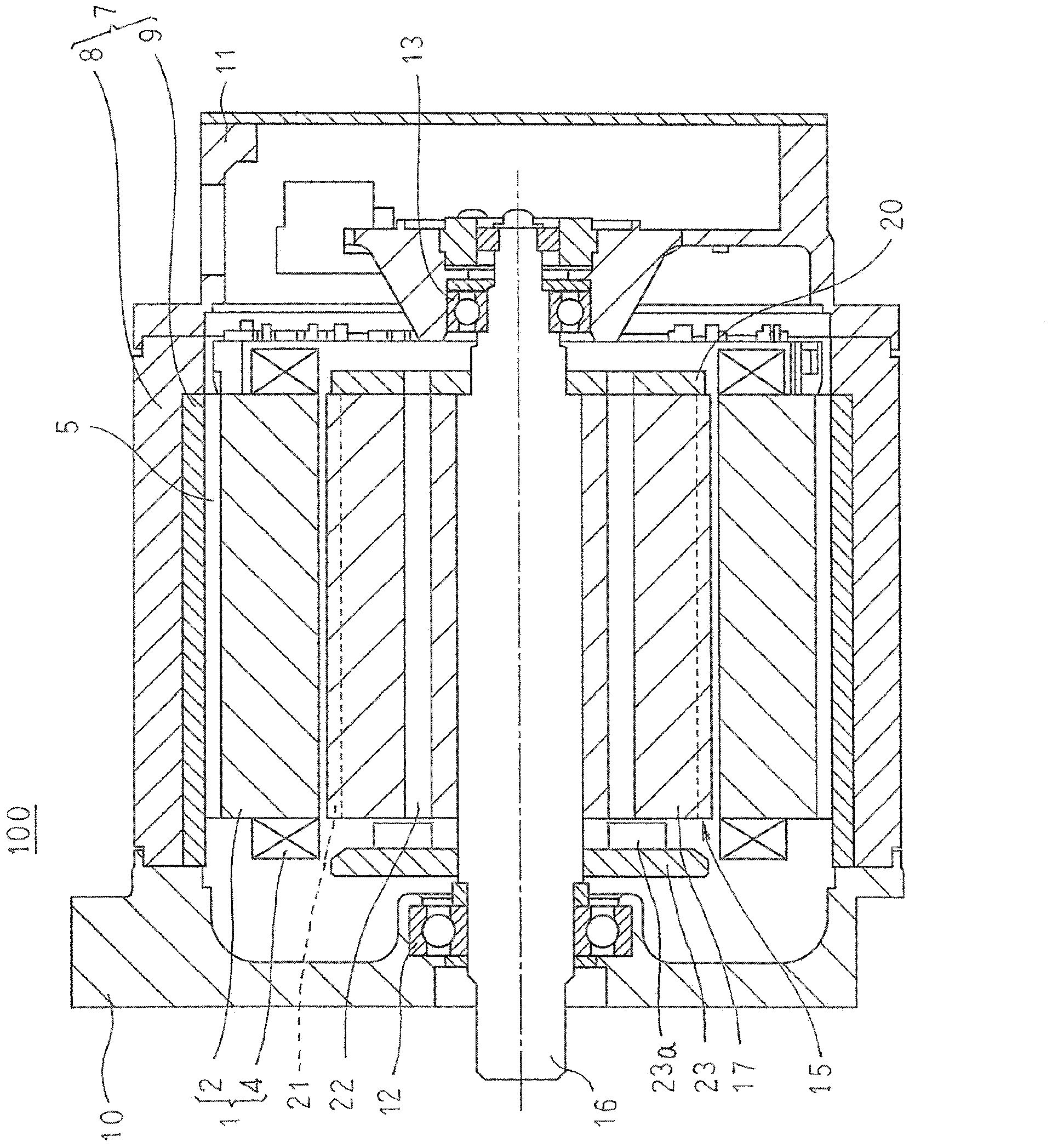
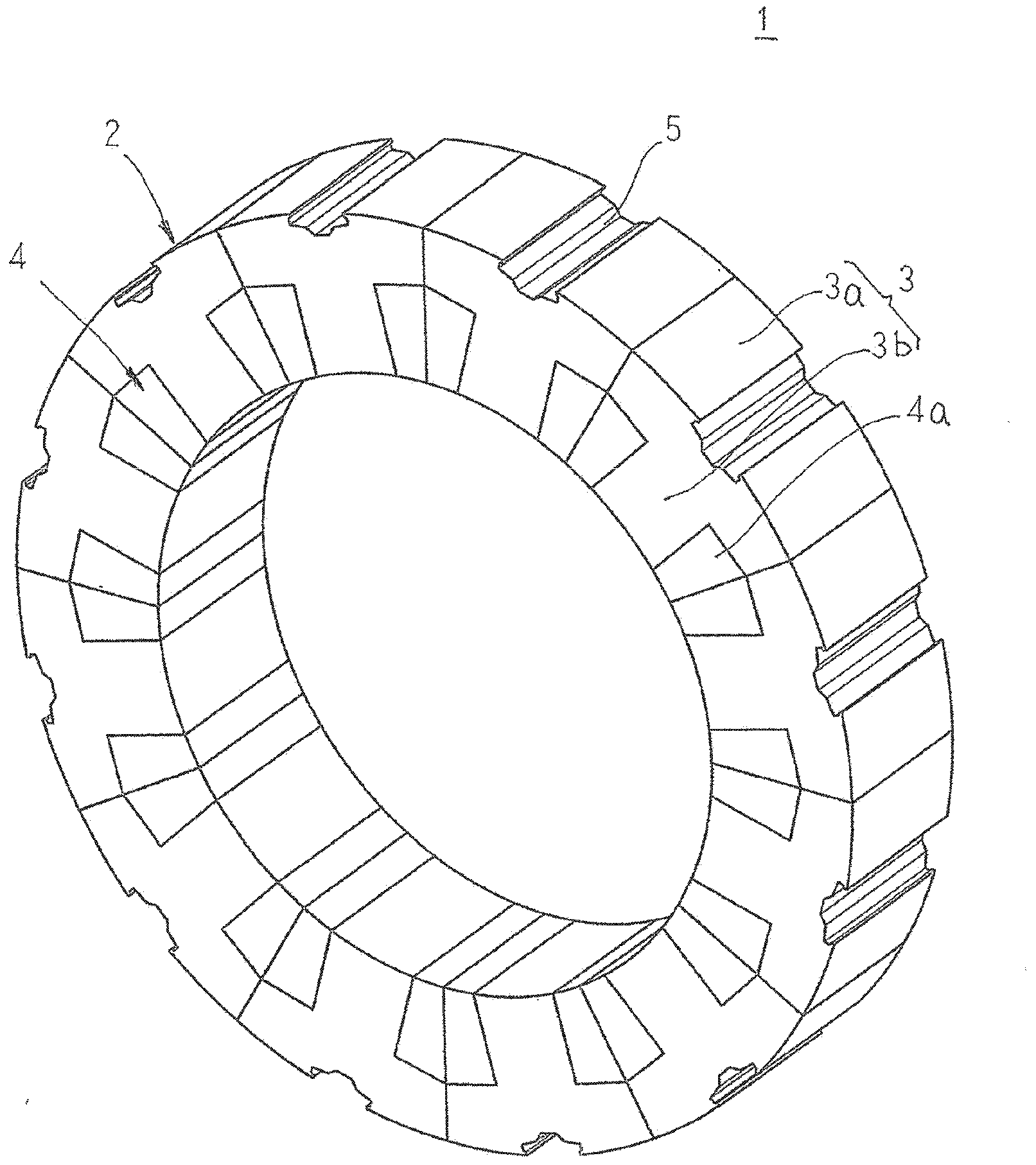
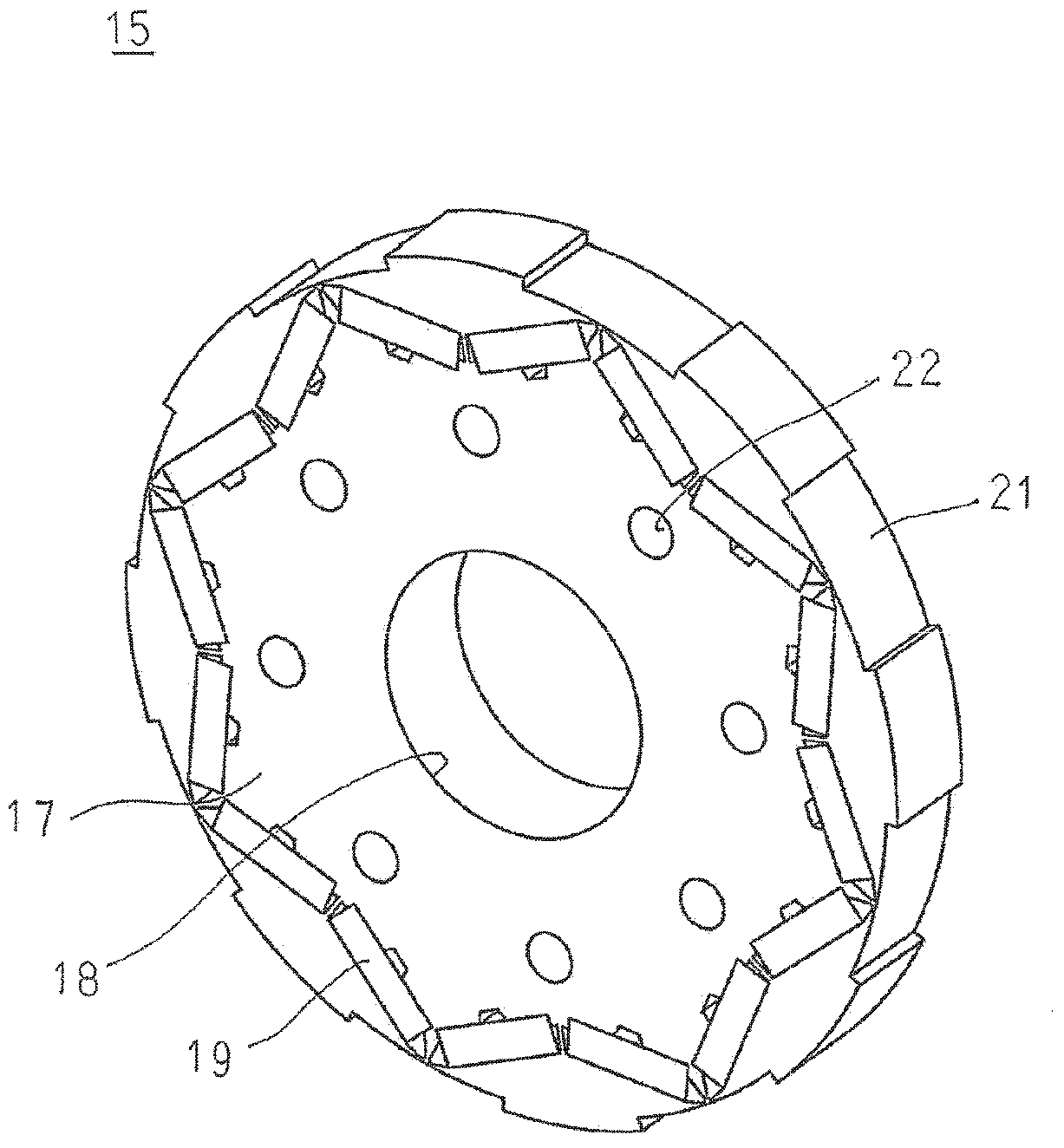
[0046] figure 1 is a sectional view showing a permanent magnet embedded rotating electrical machine according to Embodiment 1 of the present invention, figure 2 is a perspective view showing a stator in a permanent magnet embedded rotating electrical machine according to Embodiment 1 of the present invention, image 3 is a perspective view showing a rotor core in a permanent magnet embedded rotating electrical machine according to Embodiment 1 of the present invention, Figure 4 It is a perspective view illustrating a state in which a rotor core is assembled to a stator in a permanent magnet embedded rotating electrical machine according to Embodiment 1 of the present invention, Figure 5 It is a cross-sectional view illustrating the flow of cooling air in the permanent magnet-embedded rotating electrical machine according to Embodiment 1 of the present invention. In addition, in figure 2 and Figure 4 In , for convenience of illustration, the coil end is omitted. In ad...
Embodiment approach 2
[0062] Figure 7 is a sectional view showing a permanent magnet embedded rotating electrical machine according to Embodiment 2 of the present invention, Figure 8 It is a sectional view explaining the flow of cooling air in the permanent magnet embedded rotating electrical machine according to Embodiment 2 of the present invention. In addition, in Figure 8 In , arrows indicate airflow.
[0063] exist Figure 7 Among them, the flow path groove 25 has the same axial length as the axial length of the stator core 2, and the inner peripheral surface of the outer frame 8 is displaced toward the front side with respect to the stator core 2 over the entire circumference in the circumferential direction. formed by depressions. The inner frame 9 is fitted and fixed inside the outer frame 8 , and a cylindrical gap 26 configured to close the opening of the flow path groove 25 is formed between the outer frame 8 and the inner frame 9 . In addition, twelve inlet holes 27 and twelve ou...
Embodiment approach 3
[0072] Figure 9 It is a sectional view showing a permanent magnet embedded rotating electrical machine according to Embodiment 3 of the present invention. In addition, in Figure 9 In , arrows indicate airflow.
[0073] exist Figure 9 Among them, the cooling air guide portion 29 is formed on the inner wall surface of the front frame 10 from the outer diameter side of the centrifugal fan 23 to the frame 7 . The cooling air guide portion 29 is formed by bending the inner wall surface of the front frame 10 in an arc shape so that the distance between the inner wall surface of the front frame 10 and the frame 7 in the axial direction is gradually shortened from the outer diameter side of the centrifugal fan 23 toward the radially outer side. of.
[0074] In addition, other structures are the same as those in the second embodiment above.
[0075] In the permanent magnet embedded type rotating electrical machine 102 thus constituted, the centrifugal fan 23 rotates synchronous...
PUM
 Abstract
Description
Claims
Application Information