A suspension carrier system

A technology of suspension and load-carrying devices, which is applied in the field of delivery systems, can solve the problems of the complexity of air traffic management of small domestic aircraft, the inability to popularize ordinary vehicles, and high cost of use, so as to reduce construction costs, low construction costs, and lower requirements Effect

Inactive Publication Date: 2016-08-17
BEIJING KANGHUAYUAN SCI TECH CO LTD +1
View PDF5 Cites 3 Cited by
  • Summary
  • Abstract
  • Description
  • Claims
  • Application Information

AI Technical Summary

Problems solved by technology

Domestic small aircraft is also an important classification, but due to the complexity and difficulty of air traffic management for many domestic small aircraft, its use has been greatly restricted, and it has also brought high use costs, which cannot be used as a common means of transportation

Method used


Image

  • A suspension carrier system
  • A suspension carrier system
  • A suspension carrier system

Examples


Embodiment 1

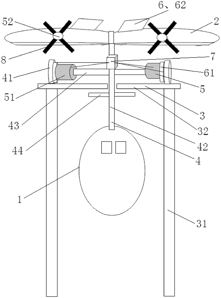
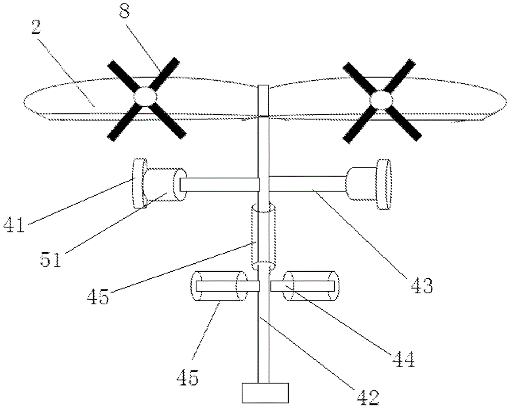
[0049] Such as figure 1 As shown, the running track 3 includes several track supports 31 arranged at intervals along the track running direction, and two pairs of tracks 32 are arranged in parallel at intervals on the track supports 31, and the connecting device 4 includes a vertical shaft 42, and the vertical shaft 42 is located on the two inner rails 32 The upper end of the vertical shaft 42 is connected to the flight wing 2, and the lower end of the vertical shaft 42 is connected to the carrying device 1. At least one wheel shaft 43 is arranged on the vertical shaft 42 between the flying wing 2 and the running track 3, and the two ends of each wheel shaft 43 are respectively connected with a wheel 41 driven by a wheel motor 51, and each wheel 41 is on the two outer rails 32. Operation; a limit rod 44 is arranged on the vertical shaft 42 between the carrying device 1 and the running track 3, and a contact feedback device is arranged between the limit rod 44 and the track 32,...

Embodiment 2

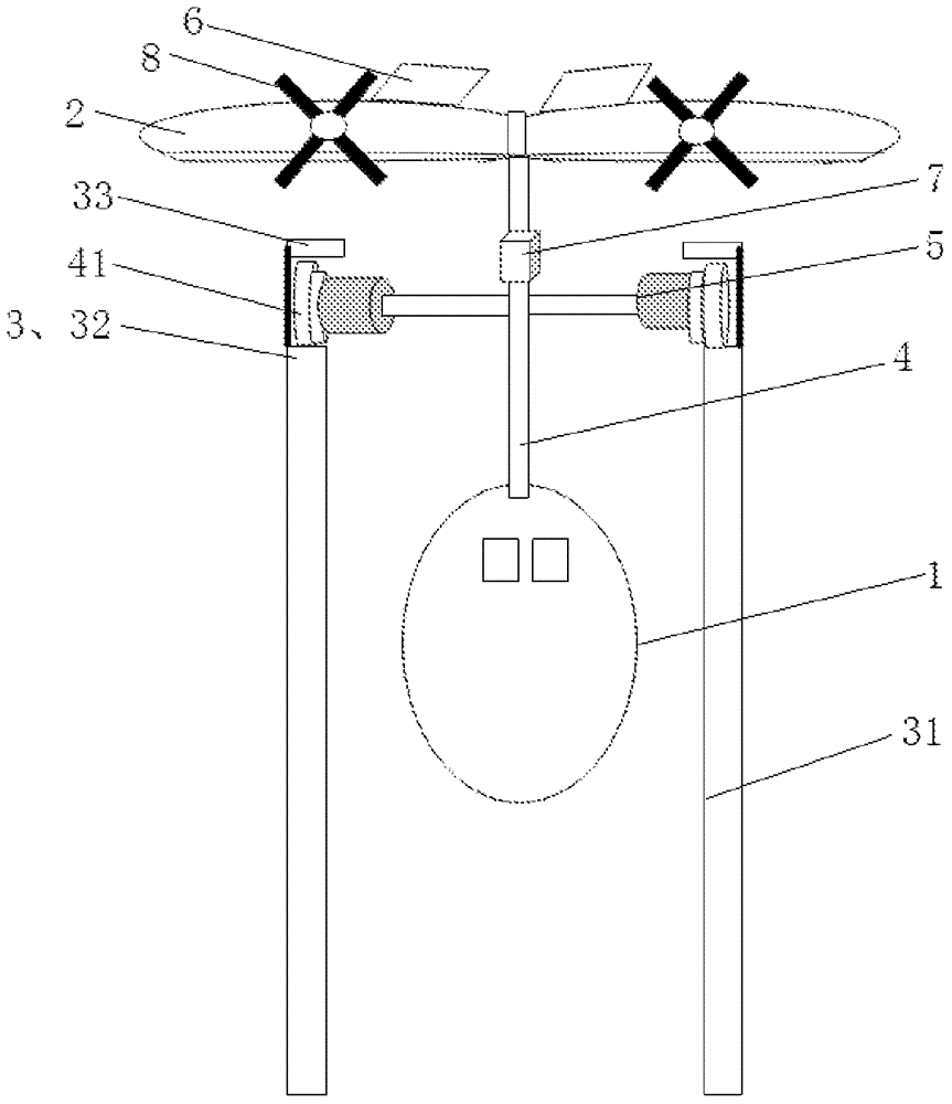
[0053] Such as image 3 As shown, the difference between the present embodiment and the first embodiment is that two rails 32 are arranged in parallel at intervals on the rail bracket 31, and a limiting track 33 is respectively arranged above the two rails 32, and the limiting track 33 and the track 32 Between them is the operating space for limiting the suspension height of the wheels 41. A contact feedback device is provided at the bottom edge of the limit rail 33 to send feedback information to the control device 7, and the control device 7 controls the flying wing 2 to drive the wheels 41 to limit the suspension height. Running in the running space, now it is not necessary to set the limit rod 44.

[0054] When the above-mentioned embodiment is running: after the device of the present invention is installed, start the driving device 5, and the wheel 41 is driven by the wheel motor 51 to rotate, and runs on the track 32. As the speed of the wheel 41 accelerates, the flying ...

Embodiment 3

[0056] Such as Figure 4 As shown, the difference between the present embodiment and the second embodiment is: each track 32 and the limit track 33 above it are oppositely provided with a pair of ribs 34 extending along the running direction of the track 32, and between the two ribs 34 is a limit. The running space of the suspension height of the wheel 41 corresponds to the two convex ribs 34 , a circle of grooves is arranged around the wheel 41 , and the wheel 41 is located in the running space limited by the two convex ribs 34 . A contact feedback device is provided on the bottom rib 34 of the limiting track 33 to send feedback information to the control device 7, and the control device 7 controls the flying wing 2 to drive the wheels 41 to run in the operating space limited by the suspension height.

[0057] When the above-mentioned embodiment is running: after the device of the present invention is installed, start the driving device, and the wheel 41 is driven by the whee...


PUM


Abstract

A suspension type carrying system, comprising a running track (3), a carrying device (1), a flight wing (2), a connecting device (4), a driving device (5), a braking device (6) and a control device (7) ); the flight wing (2) is a wing-like structure on more than one; the connecting device (4) comprises a vertical shaft (42) and a wheel shaft (43) connected to the vertical shaft (42), and each extension of the wheel shaft (43) The outlet end is provided with a wheel running on the running track (3); the flying wing (2) is connected above the bearing device (1) through the connecting device (4); the running track (3) is provided with a limit wheel suspension height The driving device (5) at least includes a wheel driving device (51) for driving the wheels to run; the braking device (6) includes a wheel braking device (61) and a flight wing The braking device (62), the driving device (5), the braking device (6) and the feedback device are connected to the control device (7), and the control device collects the feedback device information and sends instructions to the driving device and the braking device. The carrier system is an amphibious carrier, with low construction cost and good energy-saving effect.

Description

technical field [0001] The invention relates to a carrying system, in particular to a suspension carrying system. Background technique [0002] In our life, the commonly used means of transportation are automobiles, trains, airplanes, ships, electric vehicles, motorcycles, bicycles, etc. Among them, there are many types of cars, which can be divided into passenger cars specially used for people, including small cars and large passenger cars; trucks specially or mainly used to carry goods, including ordinary trucks, special vehicles, dump trucks, tractors etc.; special-purpose vehicles for construction projects, municipal public utilities, agricultural, racing vehicles, etc. According to the adaptability of the car to the road, it is divided into ordinary cars and off-road vehicles. According to the type of vehicle power plant, it is divided into piston type internal combustion engine vehicle, electric vehicle and gas turbine vehicle. There are also many types of aircraft....

Claims


Application Information

Patent Timeline
Patent Type & Authority Patents(China)
IPC IPC(8): B61B13/08B61B3/02B61B3/00
CPCB61B3/02B61B5/00B61C11/06B61C15/00Y02T30/00B61B15/00
Inventor 刘马文
Owner BEIJING KANGHUAYUAN SCI TECH CO LTD
Why Eureka
Try Eureka