
Powder injection molding feeding manufacturing equipment

A technology of powder injection molding and equipment, which is applied in the field of powder injection molding, can solve the problems of the influence of the feed preparation process, reduce production efficiency, and fail to prepare feed, so as to reduce the crushing process, save labor, and reduce reheating and temperature rise. Effect

Active Publication Date: 2014-11-19
DONGGUAN HUAJING POWDER METALLURGY
View PDF6 Cites 1 Cited by
  • Summary
  • Abstract
  • Description
  • Claims
  • Application Information

AI Technical Summary

Problems solved by technology

[0002] Powder injection molding mainly includes metal powder injection molding (Metal Powder Injection Molding, referred to as MIM) and ceramic powder injection molding (Ceramic Powder Injection Molding, referred to as CIM), the traditional powder injection molding feed preparation process is: batching→mixing → crushing → extrusion granulation, and the equipment used includes at least two or more of kneader (or internal mixer, high-speed mixer), crusher, screw extruder, and granulator, and each equipment is independent Working, transferring materials between multiple devices in each process not only reduces production efficiency, but also easily causes material pollution during the transfer process, which leads to unfavorable factors such as changes in the physical and chemical properties of the materials, resulting in the entire feeding preparation process being affected. Affected, or even unable to produce the feed that meets the requirements

Method used


Image

  • Powder injection molding feeding manufacturing equipment
  • Powder injection molding feeding manufacturing equipment
  • Powder injection molding feeding manufacturing equipment

Examples


Embodiment Construction

[0020] The present invention will be further described below with reference to the accompanying drawings and in combination with preferred embodiments.

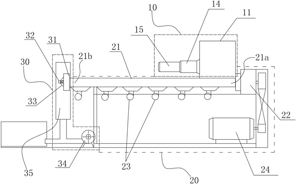
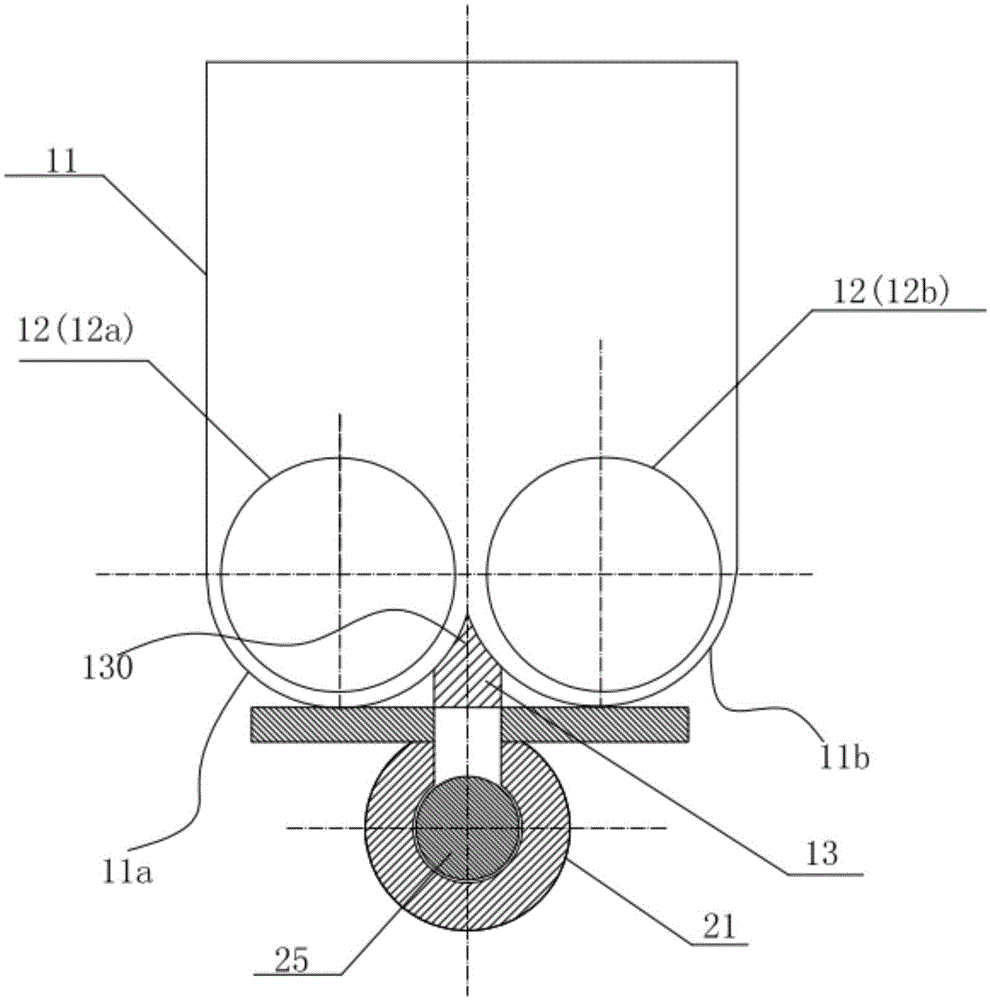
[0021] The present invention provides a figure 1 The equipment shown is used to prepare powder injection molding (PIM) feedstock, including metal powder injection molding (MIM) and ceramic powder injection molding (CIM) feedstock. Such as figure 1 As shown, the equipment includes a kneading device 10, an extruding device 20 and a pelletizing device 30, the discharge port of the kneading device 10 communicates with the inlet port 21a of the barrel 21 of the extruding device 20, and the pelletizing device 30 is connected to the extruding device 20. The outlet end 21b of the barrel 21 of the device 20, so that the powder material directly enters the extruding device 20 after being kneaded by the kneading device 10, and directly enters the pelletizing device 30 after passing through the extruding device 20 for hot-cut air-cooled...


PUM


Abstract

The invention discloses powder injection molding feeding manufacturing equipment which comprises a kneading device, an extruding device and a grain cutting device. A discharge outlet of the kneading device is communicated with a barrel inlet end of the extruding device, the grain cutting device is connected to a barrel outlet end of the extruding device, and powder materials are kneaded by the kneading device, then are directly fed into the extruding device, pass the extruding device and then are directly fed into the grain cutting device to be subjected to hot-cutting air-cooled granulation. The powder injection molding feeding manufacturing equipment for realizing powder injection molding feeding manufacturing effects has the advantages that large-scale continuous operation with high production efficiency can be carried out; the hot-state materials can be directly fed into follow-up machining links, accordingly, reheating temperature rise required by granulation procedures can be reduced, and energy consumption can be greatly decreased; labor can be saved, the efficacy of the equipment can be improved, the productivity can be enhanced, and the production cost can be reduced; crushing procedures which are carried out after intermediate cooling and solidifying can be reduced, dust can be prevented in material crushing procedures, and accordingly operation environments can be improved.

Description

technical field [0001] The invention relates to the technical field of powder injection molding, in particular to a device for preparing feed materials for powder injection molding. Background technique [0002] Powder injection molding mainly includes metal powder injection molding (Metal Powder Injection Molding, referred to as MIM) and ceramic powder injection molding (Ceramic Powder Injection Molding, referred to as CIM), the traditional powder injection molding feed preparation process is: batching→mixing → crushing → extrusion granulation, and the equipment used includes at least two or more of kneaders (or internal mixers, high-speed mixers), crushers, screw extruders, and granulators, and each equipment is independent Working, transferring materials between multiple devices in each process not only reduces production efficiency, but also easily causes material pollution during the transfer process, which leads to unfavorable factors such as changes in the physical an...

Claims


Application Information

Patent Timeline
Patent Type & Authority Applications(China)
IPC IPC(8): B22F3/115
Inventor 庞前列王长明彭毅萍
Owner DONGGUAN HUAJING POWDER METALLURGY
Learn More