Oil spill cleaning ship on water and control method

An oil spill cleaning and controller technology, which is applied in the cleaning of open water surfaces, water conservancy projects, general water supply conservation, etc., can solve the problems of secondary pollution, such as the oil spill treatment effect and monitoring of the automatic oil spill recovery device on the sea, and achieve reduction The effects of safety threats, lower usage costs, and reduced round-trip transportation time

Active Publication Date: 2016-08-17
ZHEJIANG OCEAN UNIV
View PDF9 Cites 0 Cited by
  • Summary
  • Abstract
  • Description
  • Claims
  • Application Information

AI Technical Summary

Problems solved by technology

[0009] The purpose of the invention is to overcome the secondary pollution caused by the sea oil spill treatment method in the prior art and the inability of the automatic oil spill recovery device to monitor the oil spill treatment effect, and to provide a method that can control the oil spill treatment effect. Energy-saving oil spill cleaning ship and control method for monitoring and generating electricity

Method used


Image

  • Oil spill cleaning ship on water and control method
  • Oil spill cleaning ship on water and control method
  • Oil spill cleaning ship on water and control method

Examples


Embodiment 1

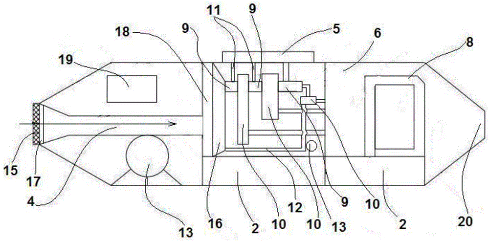
[0070] Such as figure 1 , figure 2 The shown embodiment is an oil spill cleaning ship on water, including a controller 1, two ballast tanks 2 arranged on the hull, a floating body 3 arranged on the lower surface of the hull, and a water inlet pipe 4 arranged at the head of the hull , the oil-water separation system connected with the water outlet of the water inlet pipe, the oil storage tank 5 connected with the oil-water separation system, the water storage tank 6 connected with the oil-water separation system, the wave generator located in the water storage tank and the Part of the power system 8;

[0071] The oil-water separation system includes three stages of oil-water separators 9 arranged in sequence from front to back, and liquid storage tanks 10 are arranged behind the oil-water separators at all levels, and electromagnetic valves are arranged between the water outlets of the liquid storage tanks and the oil-water separators. The oil-water separators of each stage ...

Embodiment 2

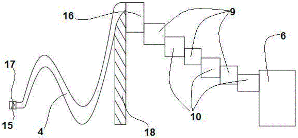
[0094] In Embodiment 2, a sewage volume regulating box 16 is provided between the first-stage oil-water separator and the water inlet pipe, a water level sensor 14 is arranged in the sewage volume regulating box, and an electromagnetic flow control valve 17 is provided at the front end of the water inlet pipe; The liquid tank is connected with the sewage volume regulating tank through the return water pipe; the electromagnetic flow control valve and the water level sensor are both electrically connected with the controller. Other structural parts in Embodiment 2 are the same as in Embodiment 1.

[0095] Step b in Example 1 is replaced by the following steps:

[0096] The standard range of water level is set in the controller, and the standard range of water level is 30% to 85% of the height of the sewage volume adjustment tank;

[0097] When the oil content is greater than or equal to W, the controller controls the electromagnetic valve on the return water pipe to open, and t...


PUM


Abstract

The invention discloses an oil spill cleaning ship on water and a control method thereof, comprising a controller arranged on the hull, several ballast tanks, a water inlet pipe, an oil-water separation system connected with the water inlet pipe, and an oil storage device connected with the oil-water separation system Tank and water storage tank, wave generators in the water storage tank and power system at the rear of the hull; floating bodies are arranged on the lower surface of the hull; the oil-water separation system includes n-level oil-water separation systems arranged in sequence from front to back Separator, all levels of oil-water separators are equipped with liquid storage tanks. In the present invention, the oil spill cleaning ship on the water is semi-submerged in the water, less affected by wind and waves, and can work under harsh sea conditions; it does not need to transport the sewage to the shore for further treatment, reducing the time of back and forth transportation, and can continue to work, with high work efficiency high feature.

Description

technical field [0001] The invention relates to the technical field of oil pollution treatment on water, in particular to an energy-saving oil spill cleaning ship on water capable of monitoring the oil spill treatment effect and generating power and a control method. Background technique [0002] With the continuous development of the world economy, the total energy consumption is increasing day by day. As one of the most important energy sources, the consumption of oil is also increasing rapidly. According to data from the Energy Information Administration of the U.S. Department of Energy, the global oil demand in 2012 was 89.05 million barrels per day. China is the main oil consumer. According to domestic data, China consumed 439 million tons of oil in 2010 and 4.7 million tons in 2011. billion tons, and consumed 493 million tons of oil in 2012. China has become the world's second largest oil consumer. [0003] There are many unsafe factors in the production, transportati...

Claims


Application Information

Patent Timeline
Patent Type & Authority Patents(China)
IPC IPC(8): B63B35/32E02B15/10
CPCY02A20/204
Inventor 魏东泽顾恩凯庄宁钱柯炜
Owner ZHEJIANG OCEAN UNIV
Why Eureka
Try Eureka