Semi-submersible type overwater overflow oil cleaning ship and control method thereof

An oil spill cleaning and semi-submersible technology, which is applied in the field of oil pollution treatment on water, can solve the problems that the automatic oil spill recovery device for secondary pollution can not deal with oil spills, monitor and other problems, so as to reduce safety threats, reduce use costs, and reduce work costs. high efficiency effect

Active Publication Date: 2014-11-19
ZHEJIANG OCEAN UNIV
View PDF7 Cites 15 Cited by
  • Summary
  • Abstract
  • Description
  • Claims
  • Application Information

AI Technical Summary

Problems solved by technology

[0009] The purpose of the invention is to overcome the secondary pollution caused by the sea oil spill treatment method in the prior art and the inability of the automatic oil spill recovery device to monitor the oil spill treatment effect, and to provide a method for monitoring the oil spill treatment effect. Energy-saving semi-submersible oil spill cleaning ship and its control method for monitoring and using cleaned water to generate electricity

Method used


Image

  • Semi-submersible type overwater overflow oil cleaning ship and control method thereof
  • Semi-submersible type overwater overflow oil cleaning ship and control method thereof
  • Semi-submersible type overwater overflow oil cleaning ship and control method thereof

Examples


Embodiment 1

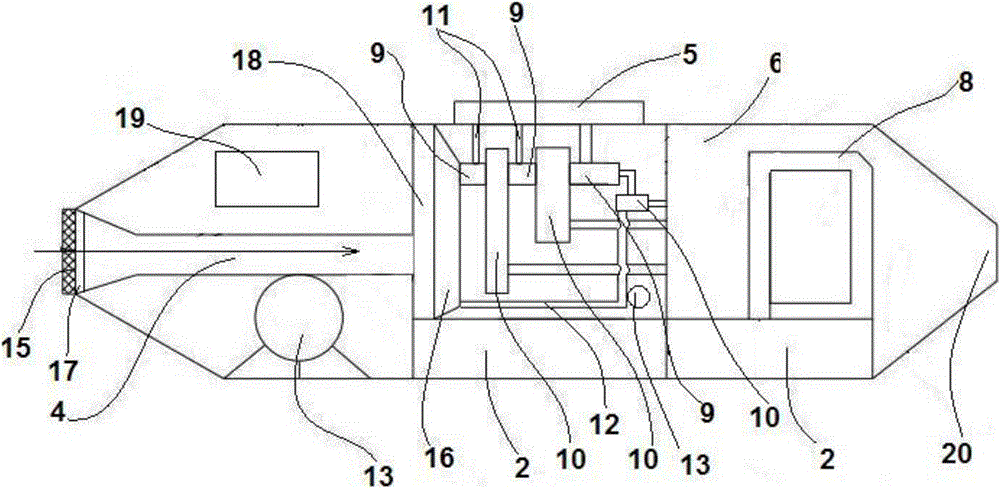
[0073] like figure 1 , figure 2 The illustrated embodiment is a semi-submersible oil spill cleaning ship, including a controller 1 arranged on the hull, a wireless transceiver 21, two ballast tanks 2 and a floating body 3 for adjusting the diving depth of the hull, The water inlet pipe 4, the oil-water separation system connected with the water outlet of the water inlet pipe, the oil storage tank 5 connected with the oil-water separation system, the water storage well 6 and the power system 8 connected with the oil-water separation system; Generator 7; The floating body is located on the lower surface of the hull; The ballast tank is connected with the water inlet and outlet pipes, and the water pumps are arranged on the water inlet and outlet pipes, and a water level sensor 14 is arranged in the ballast tank;

[0074] The oil-water separation system includes 3 oil-water separators 9 and 3 liquid storage tanks 10. Solenoid valves are installed between the water outlets of th...

Embodiment 2

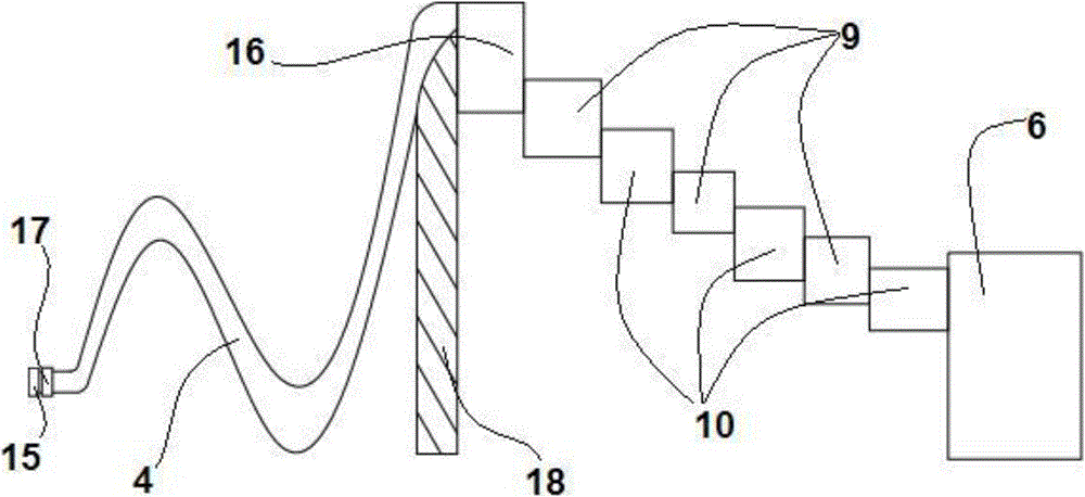
[0098]In Embodiment 2, a sewage volume regulating box 16 is provided between the first-stage oil-water separator and the water outlet of the water inlet pipe, a water level sensor 14 is provided in the sewage volume regulating box, and an electromagnetic flow control valve 17 is provided at the front end of the water inlet pipe; finally The primary liquid storage tank is connected with the sewage volume regulating tank through the return water pipe; the electromagnetic flow control valve and the water level sensor are both electrically connected with the controller. Other structural parts in Embodiment 2 are the same as in Embodiment 1.

[0099] Step b in Example 1 is replaced by the following steps, and other steps in Example 2 are the same as in Example 1.

[0100] The standard range of water level is set in the controller, and the standard range of water level is 30% to 85% of the height of the sewage volume adjustment tank;

[0101] When the oil content is greater than or...


PUM


Abstract

The invention discloses a semi-submersible type overwater overflow oil cleaning ship and a control method thereof. The semi-submersible type overwater overflow oil cleaning ship comprises a controller, a wireless transceiver, a plurality of ballast tanks and floating bodies, a water inlet pipe, an oil water separation system, an oil conservator, a water storage well and a power system, wherein the controller is arranged on a ship body; the plurality of ballast tanks and floating bodies are used for adjusting the submerging depth of the ship body; the oil water separation system is communicated with a water outlet of the water inlet pipe; the oil conservator, the water storage well and the power system are communicated with the oil water separation system; a turbogenerator is arranged in the water storage well; the floating bodies are located on the lower surface of the ship body; the ballast tanks are connected with the water inlet pipe and a water outlet pipe; water pumps are arranged on both the water inlet pipe and the water outlet pipe; water level sensors are arranged in the ballast tanks. The semi-submersible type overwater overflow oil cleaning ship has the characteristics that the ship bears a smaller wind wave effect by semi-submerging in water and can work under a severe sea condition; oil contamination can be recycled and treated on an oil overflow site, oily water is not required to be carried to a shore to be treated, back and forth transportation time is reduced, continue working can be realized as long as enough energy resources are provided, and the working efficiency is high.

Description

technical field [0001] The invention relates to the technical field of oil pollution treatment on water, in particular to an energy-saving semi-submersible oil spill cleaning ship and a control method thereof, which can monitor the oil spill treatment effect and use cleaned water to generate electricity. Background technique [0002] With the continuous development of the world economy, the total energy consumption is increasing day by day. As one of the most important energy sources, the consumption of oil is also increasing rapidly. According to data from the Energy Information Administration of the U.S. Department of Energy, the global oil demand in 2012 was 89.05 million barrels per day. China is the main oil consumer. According to domestic data, China consumed 439 million tons of oil in 2010 and 4.7 million tons in 2011. billion tons, and consumed 493 million tons of oil in 2012. China has become the world's second largest oil consumer. [0003] There are many unsafe f...

Claims


Application Information

Patent Timeline
Patent Type & Authority Applications(China)
IPC IPC(8): E02B15/10C02F1/40B63B35/32
CPCY02A20/204
Inventor 魏东泽顾恩凯程慧袁小婷
Owner ZHEJIANG OCEAN UNIV
Why Eureka
Try Eureka