Energy-saving road cutting machine

A cutting machine and sawing technology, applied in the field of energy-saving road cutting machines, can solve the problems of inconvenient charging, short continuous working time, poor working environment for staff and equipment, etc., to prevent sunburn, prolong working time, avoid The effect of direct sun damage

Inactive Publication Date: 2014-11-19
CHENGDU FENGFAN TECH
View PDF0 Cites 3 Cited by
  • Summary
  • Abstract
  • Description
  • Claims
  • Application Information

AI Technical Summary

Problems solved by technology

[0003] The purpose of the present invention is to overcome the shortcomings and deficiencies of the above-mentioned prior art, provide an energy-saving road surface cutting machine, and solve the defects of the existing road surface cutting machine that the continuous working time is too short and the charging is inconvenient; There is no shelter, and the working environment of the staff and equipment is too harsh

Method used


Image

  • Energy-saving road cutting machine
  • Energy-saving road cutting machine
  • Energy-saving road cutting machine

Examples


Embodiment 1

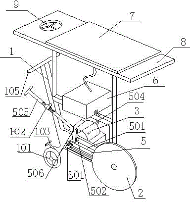
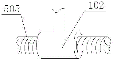
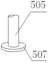
[0028] Such as Figure 1-6 As shown, the energy-saving road cutting machine includes a mounting frame 1, and a cutting saw 2, a motor 3, a battery 6 and a solar panel 7 arranged on the mounting frame 1, and a roller 101 is arranged under the mounting frame 1, and the The cutting saw 2 is installed on the mounting frame 1 through the rotator 5, and the rotator 5 includes a strip-shaped pole 501, and one end of the pole 501 is rotatably mounted on the mounting frame 1 through a pipe fitting 502, and the other A cutting saw 2 is installed at one end, and the pole 501 is aligned with the middle hole of the pipe fitting 502 to be provided with a through hole 503. The rotating shaft 301 of the motor 3 penetrates from the end of the pipe fitting 502 away from the pole 501 and is exposed from the through hole 503. The exposed part of the rotating shaft 301 from the through hole 503 is connected with the belt of the cutting saw 2, and the cutting saw 2 is driven to rotate by the motor ...

Embodiment 2

[0035] Such as Figure 8 , the structure of this embodiment is basically the same as that of Embodiment 1, except that the air inlet of the fan 9 is provided with a filter 10, because the road is generally dusty, and the eyes will be fascinated if you are not careful. It will affect the work efficiency, and it will lead to some accidents in severe cases. Set up a fan and a filter to blow out clean air, so that the environment where the staff is located is relatively clean, not only comfortable to work, but also speeds up the work efficiency.

Embodiment 3

[0037] Such as Figure 9 , the structure of this embodiment is basically the same as that of Embodiment 2, the difference is that a protective stopper 4 is provided at the cutting saw 2 on the pole 501, the protective stopper 4 wraps the cutting saw 2, and the lower end of the protective stopper 4 is open , the cutting saw 2 is exposed at the opening. The protection block 4 one is to prevent debris from splashing upwards and hurt the staff, and the other is to prevent the staff from accidentally touching the cutting saw 2 and causing personal injury.


PUM


Abstract

The invention discloses an energy-saving road cutting machine. The energy-saving road cutting machine comprises a mounting rack (1), and a cutting saw (2), a motor (3), a storage battery (6) and a solar panel (7), which are arranged on the mounting rack (1), wherein a horizontal panel (8) is also arranged on the mounting rack (1) and completely covers the whole mounting rack (1), the solar panel (7) is placed on the horizontal panel (8), and a fan (9) is arranged at a position of the panel (8), directly facing a handle (105). The energy-saving road cutting machine has the beneficial effects that the solar panel is arranged for supplying power, so that the working time of the equipment can be prolonged; the panel capable of blocking sunlight is arranged, therefore, the machinery equipment is prevented from damage caused by shining in the sun, and workers are prevented from sunburning and are protected; and the fan is arranged at a position of the panel, aligning with the worker, so that the fan can be started to blow air to the worker in hot weather and the working comfort is improved.

Description

technical field [0001] The invention relates to a cutting device, in particular to an energy-saving road surface cutting machine. Background technique [0002] At present, the speed of road construction in cities or villages is getting faster and faster, and there are more and more roads, but either because the quality of supervision is not high, or because the flow of people and vehicles is too heavy, the roads are too burdened, and the cracks and damage on the roads are serious. When the road damage is partial, it is generally used to dig out the debris manually. After repairing the road, the planing and chiseling process generally uses a road cutting machine. In terms of power supply, it is very inconvenient. Generally, batteries are used for power supply, and the continuous power supply time is very short. In summer, there is no shelter on the road, and the working environment under direct sunlight is very bad, which has a bad impact on the health of the staff and also ...

Claims


Application Information

Patent Timeline
Patent Type & Authority Applications(China)
IPC IPC(8): E01C23/09
Inventor 代膨岭
Owner CHENGDU FENGFAN TECH
Why Eureka
Try Eureka