
Tensioned anchorage device and using method of tensioned anchorage device

An anchoring device and tensioning technology, applied in the direction of structural elements, building components, building reinforcements, etc., can solve the problems of difficult fixing and bonding of fiber boards, bending deformation and wear of tension rods, and achieve easy pasting and fixing. Tension uniformity, clear effect of overall force transmission

Inactive Publication Date: 2014-11-19
RAILWAY ENG RES INST CHINA ACADEMY OF RAILWAY SCI +1
View PDF7 Cites 14 Cited by
  • Summary
  • Abstract
  • Description
  • Claims
  • Application Information

AI Technical Summary

Problems solved by technology

The tension anchor system generally adopts a concentric tension method to ensure the axial force of each component of the tension anchor system. Due to the structural constraints of the jack and the anchor seat at the tension end, this system will inevitably cause the fiber sheet to be far away from the surface of the structure. The distance from the surface of the structure is generally greater than 6cm, which makes it difficult to fix and bond the fiber sheet to the surface of the structure; although the eccentric stretching method can make the fiber sheet close to the surface of the structure, due to the distance between the axis of the jack and the tension rod and the fiber sheet The misalignment of the axes will inevitably lead to bending deformation and local wear of the tension rod
Therefore, the existing tension anchoring system will not only increase the difficulty of on-site installation and construction, reduce the reliability of the mechanical performance of the reinforcement system, but also occupy a large clearance near the structure or have a great impact on the traffic below the structure
[0005] In addition, in the existing tension anchoring system, the assembly at the tension end of the fiberboard must first penetrate the tension reaction plate in the prefabrication stage in the factory, and then install the anchor fixture. The existence of the tension reaction plate increases the coil Difficulty in packaging, on the one hand, tensioning the reaction plate during the transportation of the assembled parts is easy to wear the fiber plate
At present, there is a tension reaction plate that is connected and assembled from upper and lower parts in the thickness direction. The tension reaction plate has a preset notch for the fiber plate to pass through. Although this tension reaction plate can It can be assembled at the construction site, but the overall rigidity of the assembled tension reaction plate is small, and the assembly accuracy of the tension reaction plate is not easy to guarantee, which may easily lead to deformation, dislocation and damage of the assembled tension reaction plate. Uneven force, so it is not easy to ensure the uniformity of tension of fiberboard

Method used


Image

  • Tensioned anchorage device and using method of tensioned anchorage device
  • Tensioned anchorage device and using method of tensioned anchorage device
  • Tensioned anchorage device and using method of tensioned anchorage device

Examples


Embodiment approach 1

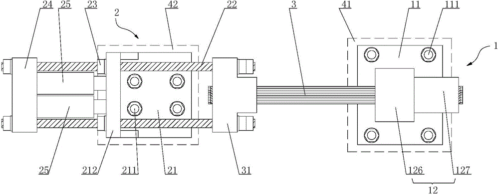
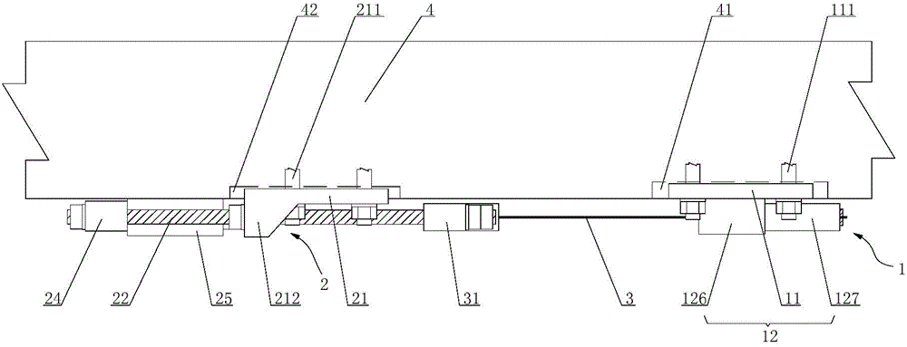
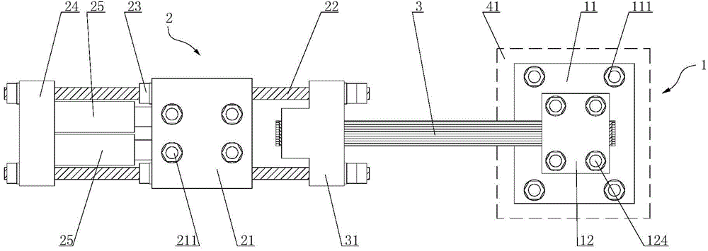
[0063] Such as Figure 1-6 As shown, the present invention provides a tension anchoring device, which includes a fixed end structure 1, a tension end structure 2 and a fiberboard 3, wherein: the fixed end structure 1 has a fixed end anchor seat 11, and the fixed end anchor seat 11 A fixed end clamp 12 is connected to it; the tension end structure 2 has a tension end anchor seat 21, and two tension rods 22 are pierced on the tension end anchor seat 21, and the two tension rods 22 are far away from the fixed One end of the end structure 1 is connected with a lock nut 23 and a rear reaction force plate 24, the lock nut 23 abuts against the anchor seat 21 of the tension end, and the rear reaction force plate 24 is connected with the tension end A plurality of jacks 25 are arranged side by side between the anchoring seats 21; one end of the fiberboard 3 is connected with a tension end clamp 31, and the other end is connected with the fixed end clamp 12, and the tension end clamp 31...

Embodiment approach 2

[0087] Such as Figure 1-18 As shown, the present invention also provides a method for using the tension anchor device as described in Embodiment 1. The structure, working principle and beneficial effects of the tension anchor device are the same as those in Embodiment 1, and will not be repeated here. . The method of using the tension anchoring device comprises the following steps:

[0088] Step 1): Grinding, cleaning and drying the surface of the structure 4, and then applying a primer layer on the surface of the structure 4;

[0089] Step 2): Install the tensioning anchor device on the surface of the structure 4 through the fixed-end anchoring seat 11 and the tensioning-end anchoring seat 21, and install the fixed-end clamp 12 connected to one end of the fiberboard 3 on the fixed-end anchoring seat 11, the tension end clamp 31 connected to the other end of the fiberboard 3 is connected to the two tension rods 22 of the tension anchor device;

[0090] Step 3): expand the ...


PUM

PropertyMeasurementUnit
Thicknessaaaaaaaaaa
Thicknessaaaaaaaaaa

Abstract

The invention provides a tensioned anchorage device and a using method of the tensioned anchorage device. The tensioned anchorage device comprises a fixed end structure, a tensioned end structure and a fiber plate, wherein the fixed end structure is provided with a fixed end anchorage base, and a fixed end fixture is connected to the fixed end anchorage base; the tensioned end structure is provided with a tensioned end anchorage base, two tensioned rods are arranged on the tensioned end anchorage base in a penetrated mode, the ends, far away from the fixed end structure, of the two tensioned rods are connected with a locking nut and a rear counter-force plate, the locking nut abuts against the tensioned end anchorage base, and a plurality of jacks are arranged between the rear counter-force plate and the tensioned end anchorage base side by side; one end of the fiber plate is connected with a tensioned end fixture, the other end of the fiber plate is connected with the fixed end fixture, and the tensioned end fixture is connected with the ends, close to the fixed end structure, of the two tensioned rods. By means of the tensioned anchorage device and the using method of the tensioned anchorage device, reliable connection between the fiber plate and a structural object can be achieved, the tensioned uniformity of the fiber plate is guaranteed, the tensioned anchorage device is small in size, flexible in arrangement and rapid and convenient to construct.

Description

technical field [0001] The present invention relates to a tension anchoring device and its usage method, in particular to a tensioning anchorage device applied in the field of structural reinforcement engineering and its usage method. Background technique [0002] At present, as an excellent tensile material, high-strength fiberboard has been widely used in the field of structural reinforcement engineering. From the point of view of the strengthening effect of structures, the reinforcement effect of directly pasting the fiber board on the surface of the structure is not obvious, and the fiber board is easy to peel off when the structure is seriously damaged; and the metal anchor clamp is used to clamp the fiber board. At the end, the reinforcement effect of prestressing the fiberboard and connecting it with the structure is very significant, and the anchoring performance is also very reliable. [0003] When the existing anchor fixture clamps the fiber sheet, stress concentr...

Claims


Application Information

Patent Timeline
IPC IPC(8): E04G21/12E04C5/12
Inventor 牛斌葛凯马林刘吉元蔡超勋李东昇
Owner RAILWAY ENG RES INST CHINA ACADEMY OF RAILWAY SCI
Learn More