Distributed optical frequency domain reflection magnetic field sensing device based on magnetostriction and demodulation method

A technology of optical frequency domain reflectance and magnetostriction, which is applied in the use of magneto-optical equipment for magnetic field measurement, magnetic field size/direction, etc., which can solve the problems of short test distance, low spatial resolution, and low magnetic field strength resolution. , to achieve the effect of improving the test distance and high spatial resolution

Active Publication Date: 2014-11-19
TIANJIN UNIV
View PDF8 Cites 24 Cited by
  • Summary
  • Abstract
  • Description
  • Claims
  • Application Information

AI Technical Summary

Problems solved by technology

[0003] At present, there are mainly two types of distributed optical fiber magnetic field sensing. The first method is based on the polarization effect to measure the magnetic field. This method has the advantages of high sensitivity and fast response, but the disadvantages of this method are: low magnetic field intensity resolution, It can only distinguish the magnetic field above 100mT. In addition, this method is seriously affected by the Faraday effect, and the test distance is relatively short, only about 15m
This method is characterized by high sensitivity to magnetic fields, but the disadvantage of this method is that the spatial resolution is low, probably above 1m

Method used


Image

  • Distributed optical frequency domain reflection magnetic field sensing device based on magnetostriction and demodulation method
  • Distributed optical frequency domain reflection magnetic field sensing device based on magnetostriction and demodulation method
  • Distributed optical frequency domain reflection magnetic field sensing device based on magnetostriction and demodulation method

Examples


Embodiment Construction

[0043] In order to make the purpose, technical solution and advantages of the present invention clearer, the implementation manners of the present invention will be further described in detail below.

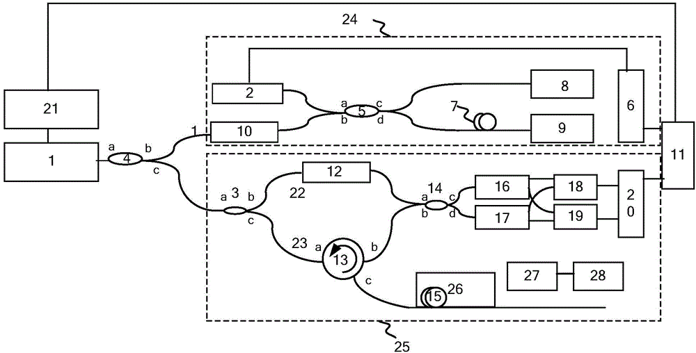
[0044] see figure 1 , the device includes: tunable laser 1: used to provide a light source for the optical frequency domain reflection system, the light source adopts a narrow linewidth linearly tunable laser light source, and its optical frequency can be linearly scanned;

[0045] 1:99 optical beam splitter 4: The output light of tunable laser 1 enters from the a port of the optical beam splitter 4, and is distributed from the b and c ports to the clock trigger system based on the auxiliary interferometer at a ratio of 1:99 24 and main interferometer 25;

[0046]Auxiliary interferometer-based clock trigger system 24: realize equal optical frequency interval sampling, the purpose of which is to suppress the nonlinear scanning of the light source; including the isolator 10, the ...


PUM


Abstract

The invention discloses a distributed optical frequency domain reflection magnetic field sensing device based on magnetostriction and a demodulation method, relating to the technical field of distributed optical fiber sensing instruments. The device comprises a main interferometer which obtains a sensing signal and an auxiliary interferometer which provides a clock trigger signal for a collection device, and a detected sensing fiber is packaged on a magnetostriction material. The method comprises the steps of obtaining different beat frequency signals at main interference through a light source of linear tuning, and converting wavelength domain information to distance domain information of each position in a corresponding sensing fiber by using rapid Fourier transform. The signal on the sensing fiber is selected through a mobile window, and then the conversion to a wavelength domain is carried out through plural rapid Fourier inverse transform, namely the Rayleigh scattering spectra. According to the distributed optical frequency domain reflection magnetic field sensing device and the demodulation method, the testing distance is raised, the spatial resolution and high, the accurate positioning of a multiple-point magnetic field can be carried out at the same time, the magnetic field strength can be measured at 5.3mT to the minimum, the testing distance can reach more than 300meters, and the magnetic field positioning accuracy can reach 14centimeters.

Description

technical field [0001] The invention relates to the technical field of distributed optical fiber sensing instruments, in particular to a magnetostrictive distributed optical frequency domain reflection magnetic field sensing device and a demodulation method. Background technique [0002] With the continuous development of society, the magnetic field in important areas such as medical treatment, electric power, and nuclear industry has a particularly important impact on their safety. The distributed optical fiber magnetic field sensing system can realize magnetic field detection and positioning, and has the characteristics of long-distance monitoring, high-precision positioning, low energy dependence, high environmental tolerance, and corrosion resistance. [0003] At present, there are mainly two types of distributed optical fiber magnetic field sensing. The first method is based on the polarization effect to measure the magnetic field. This method has the advantages of high...

Claims


Application Information

Patent Timeline
Patent Type & Authority Applications(China)
IPC IPC(8): G01R33/032
Inventor 刘铁根丁振扬杜阳刘琨江俊峰冯博文
Owner TIANJIN UNIV
Why Eureka
Try Eureka