
Clutter suppression method of non-positive side-looking bistatic MIMO radar

A non-side-looking, clutter suppression technology, applied in the radar field, can solve the problems of inability to realize real-time processing, large amount of calculation in full-dimensional processing, and large number of independent and identically distributed clutter samples.

Inactive Publication Date: 2014-11-19
XIDIAN UNIV
View PDF4 Cites 11 Cited by
  • Summary
  • Abstract
  • Description
  • Claims
  • Application Information

AI Technical Summary

Problems solved by technology

The disadvantage of this method is that the calculation amount of the full-dimensional processing is large, and the number of independent and identically distributed clutter samples is large, and real-time processing cannot be realized in practical applications.

Method used


Image

  • Clutter suppression method of non-positive side-looking bistatic MIMO radar
  • Clutter suppression method of non-positive side-looking bistatic MIMO radar
  • Clutter suppression method of non-positive side-looking bistatic MIMO radar

Examples


Embodiment Construction

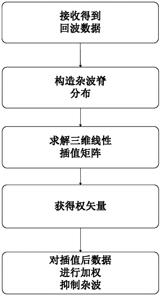
[0063] refer to figure 1 , illustrating a clutter suppression method for a non-front-looking bistatic MIMO radar of the present invention.

[0064] Step 1, the bistatic MIMO radar receives the echo data y of the mth range unit in the non-side-looking situation NSL,m , the mth distance cell is divided into N c clutter point.

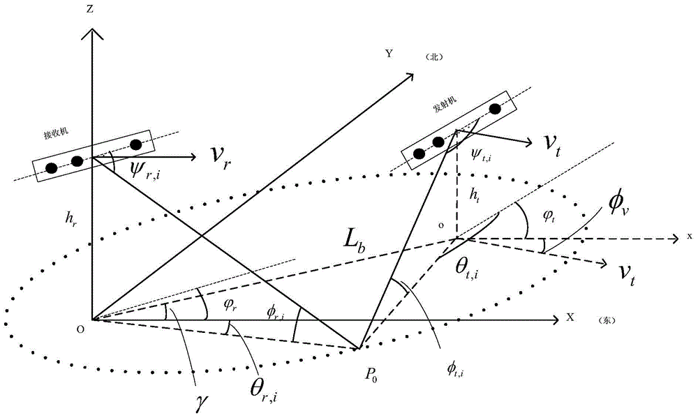
[0065] In the geometric configuration model of bistatic MIMO radar, is the angle between the flight direction of the transmitter and the axis of the transmitting array element, is the angle between the flight direction of the receiver and the axis of the receiving array element. when and is the side-looking situation of the bistatic MIMO radar, when and When at least one of is not equal to 0, it is the non-side-looking situation of the bistatic MIMO radar. Clutter points are also called clutter scatter points.

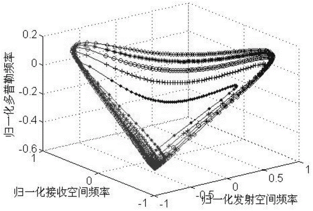
[0066] Step 2. Construct the normalized emission spatial frequency f of the i-th clutter point in the m-th range cell t,i , the ...


PUM


Abstract

The present invention discloses a clutter suppression method of a non-positive side-looking bistatic MIMO radar, belonging to the radar technology field. The method comprises the steps of (1) using the bistatic MIMO radar to receive the echo data on the non-positive side-looking condition; (2) constructing a clutter ridge distribution; (3) obtaining the clutter ridge distribution on the positive side-looking and non-positive side-looking conditions; (4) solving a three-dimensional linear interpolation matrix; (5) adding a noise calculation covariance in the interpolated echo data to obtain a weight vector; (6) weighting the interpolated data with an optimal weight to suppress the background clutter. The clutter suppression method of the non-positive side-looking bistatic MIMO radar of the present invention mainly solves the problems that on the non-positive side-looking condition, a clutter spectrum does not have the coplanarity any longer, and a three dimensional linear minimum variance method is not suitable any longer, and can eliminate a clutter distance dependence characteristic effectively, thereby improving a clutter suppression performance.

Description

technical field [0001] The invention belongs to the technical field of radar, and relates to a method for suppressing clutter of a non-side-looking bistatic MIMO radar. Background technique [0002] Radar is the abbreviation of "Radio Detection and Ranging". It emits electromagnetic waves to irradiate the area of ​​interest, finds the target according to the received echo, and measures the target's azimuth, height and other information. Among them, the bistatic radar has the advantages of concealed detection, anti-jamming and anti-fading due to the separate structure of the receiver and transmitter systems, and it is also conducive to the detection of stealth targets. But also because of this geometric structure, the distribution of the clutter power spectrum changes with the distance, showing the non-stationary characteristics of distance, that is, the clutter sampling data of different range gates do not satisfy the independent and identical distribution condition, that is...

Claims


Application Information

Patent Timeline
IPC IPC(8): G01S7/36
CPCG01S7/2928G01S13/003
Inventor 李军马玉芳郭一帆刘长赞廖桂生
Owner XIDIAN UNIV
Learn More